Home > VHDL > Logic Gates > AND Gate
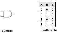
Figure below shows the symbol and the truth table of the AND gate. The AND
gate can be implemented using the data flow modelling or the behavioural
modelling. In data flow modelling of AND gate the operator AND is used to
logically AND the inputs A and B. In behavioural modelling the behaviour of
the gate is explained with the help of sequential statements.
library IEEE;
use IEEE.std_logic_1164.all;
entity AND2 is
port (A,B : in std_logic;
C : out std_logic);
end AND2;
architecture data_flow of AND2 is
begin
C <= A AND B;
end data_flow;
library IEEE;
use IEEE.std_logic_1164.all;
entity AND2 is
port (A,B : in std_logic;
C : out std_logic);
end AND2;
architecture behav of AND2 is
begin
process (A,B)
begin
if (A='0' and B = '0') then
C <= '0';
elsif (A='0' and B = '1') then
C <= '0';
elsif (A='1' and B = '0') then
C <= '0';
else C <= '1';
end if;
end process;
end behav;