Home > mini projects > HARTLEY AND COLPITTS OSCILLATOR USING OPAMP
![]()
![]() HARTLEY AND COLPITTS OSCILLATOR USING OPAMP
HARTLEY AND COLPITTS OSCILLATOR USING OPAMP
Abstract-An oscillator is a circuit that produces oscillating signals such as sine or cosine wave which is periodic in nature. They are used widely in Signal broadcasting .As we know that in today's world tuning is very important, tuning means resonance which means if some frequency is there and we want to tune with that signal so there must be a proper circuit which should be tune with signal. But while tuning there are unwanted noise which superimposes with the signal and we won't hear it properly. One such oscillator is an Hartley Oscillator and Colpitts Oscillator. They are used in Tuned circuit oscillators such that they can tuned easily with constant amplitude output.
INTRODUCTION:
H ARTLEY Oscillator is an oscillator circuit in which the oscillation frequency is determined by a tuned circuit consisting of capacitors and inductors, that is, an LC oscillator which is a tank circuit for the tuning. Here two inductors and one capacitors are used such that such that two inductors are in series which are connected in parallel with a variable capacitor. Hartley Oscillator is designed using Operational Amplifier
WHY OPERATIONAL AMPLIFIER IS USED INSTEAD OF
TRANSISTOR?
A transistor is a single electronic element. A transistor is used to perform many functions such as amplification, rectification, filtering, etc. when it is combined with other circuit elements such as resistors, capacitors etc. An operational amplifier is a combination of these transistor elements that forms a block. It is more capable than a single transistor because it contains many more circuit elements that allow for very flexible circuit configurations. It is so generally useful that it is made as an integrated circuit which is easily applied as a single circuit. An operational amplifier is the combination of many transistors and is thus able to perform much better than a single transistor. Its active stage is that gain of the opamp can be much adjusted using feedback resistors R1 and R2. In oscillator using transistor, the gain if the circuit must be equal to or slightly greater than the ratio of L1/L2. In transistorized Hartley oscillator, the gain is depends on the tank circuit elements L1 and L2 whereas in Op-amp oscillator gain is less depends on the tank circuit elements and hence provides great frequency stability.
CIRCUIT DIAGRAM:

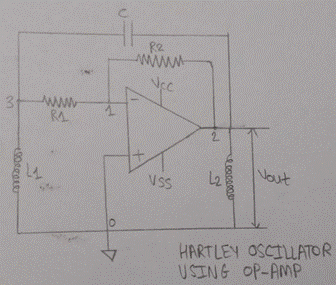
WORKING OF HARTLEY OSCILLATOR:
Here R1 and R2 are biasing resistors and the operation of this circuit is similar to the transistor version of Hartley
![]()
![]() oscillator .Here tank will generate a wave which goes to opamp. Then
this wave is stabilized and inverted by the amplifier. With the help of
variable capacitor in the tank circuit keeping the feedback ratio and
amplitude of the output constant for over a frequency range, the
frequency of the oscillator is varied. There is a possibility of mutual
inductance because of the change in current through coil induces the
current in other coil by the magnetic field which is called as mutual
inductance. It is an additional amount of inductance caused in one
inductor due to the magnetic flux of other inductor.
oscillator .Here tank will generate a wave which goes to opamp. Then
this wave is stabilized and inverted by the amplifier. With the help of
variable capacitor in the tank circuit keeping the feedback ratio and
amplitude of the output constant for over a frequency range, the
frequency of the oscillator is varied. There is a possibility of mutual
inductance because of the change in current through coil induces the
current in other coil by the magnetic field which is called as mutual
inductance. It is an additional amount of inductance caused in one
inductor due to the magnetic flux of other inductor.
MATHEMATICAL FORMULAS:
1. Frequency of oscillation:
fo = 1/ (2π √ (Leq C)) Where Leq = L1 + L2 + 2M or L1 + L2
 2. Amplifier Gain:
The amplifier gain must be selected greater than or at least equal to the ratio of two inductances
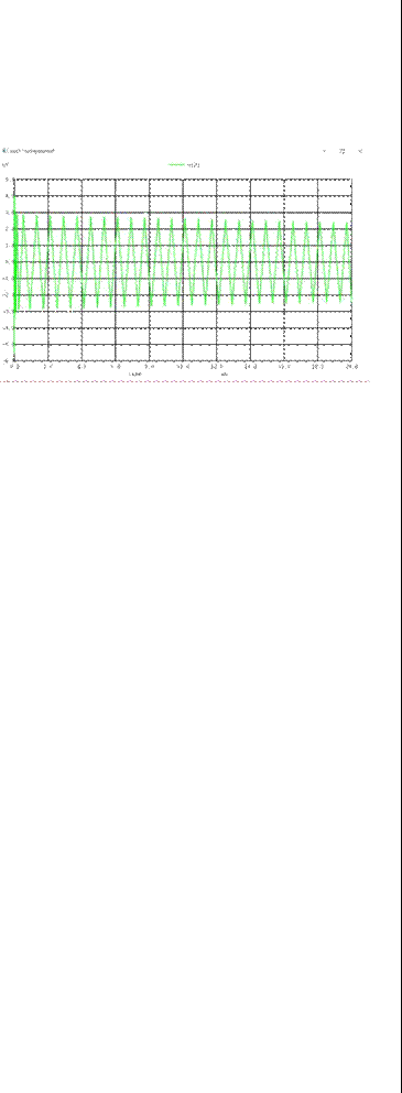
PRACTICAL OBSERVED WAVEFORM:

The output which we are getting is not a perfect for tuning as we can see in this waveform first its oscillating ie time period is very less and then such that there are sharp edges in this waveform such that time period is more which is constant
Av = L1 / L2
If mutual inductance exit between the two coils then
Av = (L1 + M) / (L2 + M)
Values which are used to in this oscillator for inductor and capacitor are as follows:
L1=1mH
L2=1mH
C=1pF
3. Theortical Frequency: fo=1.887 KHz
4. Practical Frequency: fo=1.2 KHz
As the range of operation for such oscillactor ie RF(Radio frequency) is upto 30MHz.
IMPROVEMENT:
As we know that it produces a range upto 30 MHz so we can improve the range by improving the circuit, by improving a tank circuit ie by connecting more capacitors and inductors. Here by connecting an inductor parallel across inductor frequency range can be increased drastically.
APPLICATION:
Its range is upto 30 MHz which is a wide range comparative to other oscillators.
It is used in a region where there is not much traffic of frequencies which means rural areas.
It can be used in a region where our soldiers works ie a region like high mountains where it's difficult to live in cold temperature and again less traffic of frequencies.
Because of its wide range, it can be used as a distress signal where distress signals are communicated by transmitting RF signals, making a sound audible from a distance. A distress signal indicates that a person or group of people,ship, aircraft, or other vehicle is threatened by serious danger and requires immediate assistance.
It is used in a telecommunication also.
![]()
INTRODUCTION:
C OLPITTS OSCILLATOR is the oscillator which is opposite of the Hartley Oscillator, just like the Hartley oscillator, the tuned tank circuit consists of an LC circuit
connected with the opamp ie node 2 and ground. The basic configuration is same as that of Hartley Oscillator but the basic difference is that the centre tapping of the tuned circuit is made of capacitive voltage divider network instead of pairs of inductors ie instead of two inductors now there are two capacitors which are in series and connected in parallel with an inductor. This oscillator also is designed with the help of Operational Amplifier because of better adjustable gain as in its active stage the gain of the opamp can be much adjusted using feedback resistors R1 and R2. In oscillator using transistor, the gain if the circuit must be equal to or slightly greater than the ratio of L1/L2.
WHY COLPITTS OSCILLATOR IS PREFERRED OVER HARTLEY OSCILLATOR?
As in Hartley Oscillator, there are two inductors used such that there is a chance of mutual inductance within the tank circuit such that it leads to less frequency stability. Therefore with two capacitors and one inductor only there will be no mutual inductance and stability will be more in this oscillator. Because of low impedance path of the capacitors at high frequencies Colpitts oscillator produces a better sinusoidal waveform.
CIRCUIT DIAGRAM:
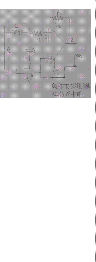
WORKING OF COLPITTS OSCILLATOR: Here R1 and R2 are the resistors where R2 is the feedback resistor and a combination of capacitors and inductors ie tank will generate a wave which is of 180 degree phase shift and goes to opamp. When the power supply is given to the circuit, there is no signal, but the small noise voltages are amplified by the op-amp. This makes the both capacitor to starts charging and discharging .Then this wave is stabilized and inverted by the amplifier such that the output we will get is of 360 degree or 0 degree .With the help of variable capacitor in the tank circuit keeping the feedback ratio and amplitude of the output constant for over a frequency range, the frequency of the oscillator is varied. Feedback depends on the values of C1 and C2. The voltage across C1 is the same as the oscillator's output voltage and that the voltage across C2 is the oscillator's feedback voltage and voltage across C1 is more than voltage across C2. We have to adjust the value of Capacitor such that the output waveform should not be distorted for large values of feedback and should not oscillate for small values of feedback.

IMPROVEMENT:
As we know that it produces a range upto 100 MHz so we can improve the range by improving the circuit, by improving a tank circuit ie by connecting more capacitors and inductors. Here by connecting a capacitor across capacitor frequency range can be increased drastically.
![]()
MATHEMATICAL FORMULA:
FREQUENCY OF OSCILLATION:
fo = 1/ (2π√ (LCeq))
Where Ceq = C1 C2 / (C1 + C2)
Values which are used in this oscillator are as follows:
C1=0.024u
C2=0.024u
L=1m
THEORTICAL FREQUENCY:
fo=45KHz
PRACTICAL OBSERVED WAVEFORM:
As we can observe in the waveform, first there is large oscillation in the initial and the amplitude decreases such that we are getting a small signal of small amplitude which sharp edges. This waveform we are getting because of voltage follower such that ie output voltage is equal to input voltage

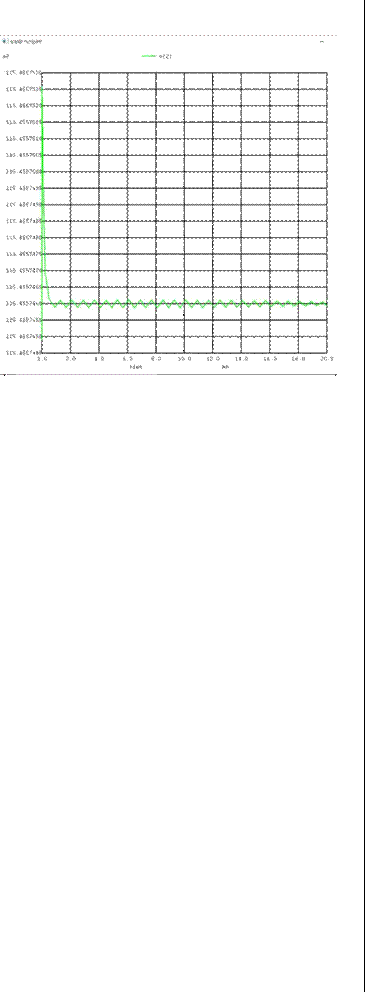
still we are not getting perfect tuned waveform.
APPLICATION:
Colpitts Oscillator produces a range of frequency upto 100MHz
It is used for distress signal where distress
signals are communicated by transmitting RF signals, making a sound audible from a distance. Such that Colpitts is preferable over Hartley, for a place where there the tuning is not as good as in urban areas like rural areas but for rural areas Hartley is enough.
But in regions like high mountains, Colpitt is very useful.
It is used in microwave application.
![]()