Home > mini projects > COMPANDING CIRCUIT USING OPAMPS
COMPANDING CIRCUIT USING OPAMPS
Abstract- Companders are widely used in communication systems to compress the dynamic range of an information signal such as speech signal before digitizing the signal.Here we have implanted the compander circuit using opamps i.e by using opamp subcircuit.It also finds its applications in tele-communication and digital signal processing sector.
I. INTRODUCTION
The word compander is just the combination of the two words compresser and expander.This process is non-linear over all but linear over short period of times.It is used for improving the signal to noise ratio of the signal,to reduce the number of bits.The basic use of compander allows signals with large dynamic range to be transmitted over smaller dynamic capability.Its applications are mostly found in tele-communication and signal processing sector.It is a common technique used for making the quantisation levels unequal there by reducing the data rate of audio signals.
II. Working
This is effectively a form of lossy audio compression.
A Compander is a non-linear circuit which provides high amplification for low input amplitude signals and low amplification for high input amplitude signals.
A compander operates in a transmitter to compress audio signals before they are transmitted and in a receiver to expand the audio signals after they are received.
An electronic circuit implementing the compander consists of a logarithmic amplifier at the transmitter for compression and an exponential amplifier at the receiver to nullify the effect caused by the compression. When an analog signal is applied at input of logarthmic Amplifier,the input signal is compressed and this is sent through channel which comprises of linear variable gain amplifier and at the receiver end,we receive this compressed signal and at end of exponential amplifier. We can retrieve the original signal which is expanded form of the compressed signal.
III. Subcircuit opamp code
*subckt_opamp.cir
.subckt opamp 1 2 6
R1 1 2 1MEG
E1 3 0 2 1 100K
C1 4 0 1.5u
E2 5 0 4 0 1
R2 5 6 100
R3 3 4 1K
.ends opamp
IV. Circuit Diagram
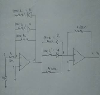
IV. Main code
*COMPANDER*
***
.include opamp1.cir
x1 2 0 3 opamp
x2 8 0 9 opamp
v1 1 0 sin(5 10 10k 0 0)
R1 1 2 1K
R2 2 5 100
R3 2 4 100
R4 2 3 10k
D1 3 4
D2 5 3
R5 3 6 100
R6 3 7 100
R7 3 8 10K
D3 8 6
D4 7 8
R8 8 9 1K
.control tran 1u 1m run
plot v(1) v(3)
plot v(1) v(9)
plot v(3) V(9)
.endc
.end
V. Output Waveforms
i/p vs compressed:
Input waveform: V(1)-green color
Compressed waveform: V(3)-red color
Compressed vs expanded:
Compressed waveform: V(3)-green color
Expanded waveform: V(9)-red color
i/p vs expanded:
Input waveform: V(1)-green color
Expanded waveform: V(9)-red color
The expanded waveformis equal to the input waveform.
VI. Applications
Compander is used in PCM for digital audio signals. Companding is also widely used in tele-communication and signal processing sector, compressing before input to analog to digital converter and then expanding after a digital to analog converter. Professional wireless microphones use this compander since the dynamic range of the microphone audio signal itself is larger than the dynamic range provided by radio transmission.
VII. Advantages
Companding reduces the bitrate required for transmission.It also reduces buzz, hiss and low-level audio tones caused by mild interference. Quantisation error and effects of noise are minimized with the use of compander.Companding reduces dynamic range so that fewer bits are needed to digitize the audio signal. Companding can improve the useful range of wireless systems as well.
VIII. Result and conclusion
To get a better noise ratio (SNR) and to minimize the noise and distortion in received signal, compander is used.By narrowing the dynamic range of signal to be amplified,the noise which will get amplified can be reduced.