Home > finite state machines > State Machine Fundamentals > Finite State Machine Diagram
Finite State Machine Diagram
Finite-State-Machine-Diagram
Default state :
The designer declares a state to be the default state. The machine transits to the default state if no transition from a given state take place. The default state is useful for debugging state diagrams.
Trap state :
The designher declares a state to be the trap state. The machine transits to the trap state on the nearest active clock edge. Further, the machine can be in a state different than S1, S2, S3 since the Sreg0 signal acquire only three values : S1, S2 or S3. Furthremore, if synthesized code tried to simulate the synthesized netlist, minimum two bits are required to encode all machine states. For a machine encoded using a 2-bit status word, we got one additional unused state.
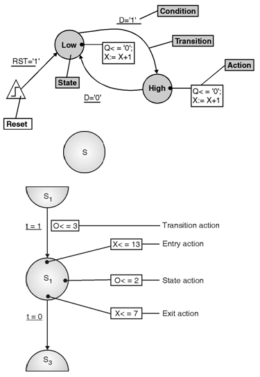
Transition :
A transition is a change of the current machine state from one state to another occurring on the active clock edge. If it evaluates to TRUE, the transition associated with this condition take the effect. Transition priorities : If two or more transitions coming out of the same state may simultaneously evaluate to TRUE, they should have different transition priorities assigned. By default, all transition on a state diagram have priority 0, which is the highest possible. A priority value can range from 0 to 9. A transition with a lower priority value takes precedence over transitions with higher priority values.
Action : Action is a set of HDL statements which assigns new values to ports, internal signals and variables. The statements that occure in actions are :
- Signals assignments
- Variable assignments
There are two basic kinds of actions :
(1) State actions :
A state action is defined for a state. It is performed when the machine transits to a specific state. The behavior of combinatorial and registered signals/ports involved in state actions is the same. The HDL statements defined in a state action are executed on the active clock edge. State actions can be used to model Moore's machines.
(2) Transition actions :
A transition action is defined for a transition. It is performed when the machine performs a specific transition from a specific state. The behavior of signal/ports involved in transition actions differs for combinatorial and registered types. Assignments to combinatorial ports/signals are executed asynchronously with changes of inputs to which the transition is sensitive. Assignments to registered ports/signals are executed only on the active clock edge. Transition actions can be used to model Mealy's machines. The two next action types are designed to reduce the number of transition actions as shown in Figure.
a) Entry actions :
An entry action is defined for a state. It is a transition action that is performed on each transition to this state.
b) Exit actions :
An exit action is defined for a state. It is a transition action that is performed on each transition from this state. Combinatorial and registered signals updated in state actions behave differently. Combinatorial signals are sensitive asynchronously to the machine inputs because they are updated by concurrent signal assignments. Registered signals are updated within the machine process so they can change only on the active clock edge. Encoding state and transition actions with variable assignments : As variables are declared in the process statement, variable assignments may occur only within the process. The location of action assignments to variables are the same as that of action assignments to registered signals. See variables and internal signals for details.
Reset :
The machine transits to a state defined as the machine's reset state if reset condition is true. The transition to the reset state is asynchronous or synchronous. A machine with the asynchronous reset transits to the reset state when reset condition becomes TRUE.