Home > mini projects > ANALOG SIGNAL DIVIDER
ANALOG SIGNAL DIVIDER
OPERATIONAL AMPLIFIER :
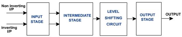
An Operational Amplifier is basically a three-terminal device which consists of two high impedance inputs, one called the Inverting Input given by a negative sign, ( - ) and the other one called the Non Inverting Input given by a positive sign ( + ).
BLOCK DIAGRAM OF OPAMP :
Non-Inverting Summing Amplifier :
A non-inverting summing amplifier can be constructed using the non-inverting amplifier configuration. The input voltages are applied to the non-inverting input terminal and a part of the output is fed back to the inverting input terminal, through voltage-divider-bias feedback.
CIRCUIT DIAGRAM :
For design of the non inverting summing circuit we have to first design the non invering amplifier which should have the required high voltage gain. After we have to select the Input resistors as large as possible according to the opamp which we are using.
A non inverting summing amplifier circuit with two inputs are shown above. The voltage inputs Vin1,Vin2 are applied to non inverting input of the opamp. Rf1 is the feedback resistor. The output voltage of the circuit is given by
Vo = (1+ (Rf/R1)) (( Vin1+Vin2)/2)
LOGARITHMIC AMPLIFIER :
Log amplifier is a linear circuit in which the output voltage will be a constant times the natural logarithm of the input. It is basically used to provide Dynamic Compression range.
CIRCUIT DIAGRAM :
I = I0 (exp(V/(Vt))-1) (I0= Reverse saturation current)
As exp(V/(Vt))>>1
I = I0 (exp(V/(Vt)))
V0= -Vf
I=Vin/R
Taking logarithm on both sides
log I = log I0 + Vf/Vt
Vt log(I/I0)=Vf
Vf=Vt log (Vin/RI0)
Vf= Vt (log(Vin/R) - log (I0))
-V0 = Vt (log(Vin/R) - log (I0))
V0= -Vt log(Vin/RIo)
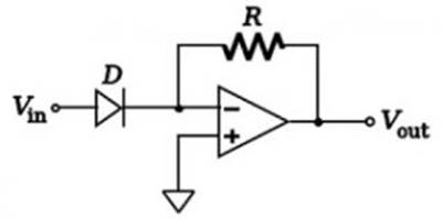
ANTILOGARITHMIC AMPLIFIER :
Anti logarithmic amplifier is an amplifier which provides output proportional to the anti log i.e. exponential to the input voltage.
CIRCUIT DIAGRAM :

The current equation of diode is given as Id = Ido (exp (V/Vt)-1)
where Ido is reverse saturation current,
V is voltage applied across diode;
Vt is the voltage equivalent of temperature
Applying KCL at inverting node of opamp
Id = (0-Vo)/R = Io(exp (Vin/V t)) (assumed Vin /Vt >> 1)
Hence V0 = -I0*R*(exp (Vin/Vt)).
Gain of Anti log amplifier K= -I0*R
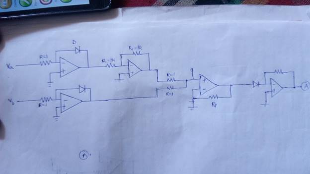
ANALOG DIVIDER CIRCUIT:
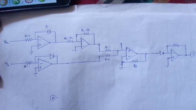
First when the input is applied to inverting terminal of logarithmic amplifier we will get -ln(Va) .Similarly at other input we will get -ln(Vb).And when -ln(Va) is applied to inverting Input of Inverting amplifier we will get ln(Va). Then both Inputs ln(Va) and -ln(Vb) are given input to non inverting summing amplifier.Therefore we will get ln(Va)-ln(Vb) which is ln(Va/Vb) and again if this is given to inverting terminal of antilogarithmic amplifier we will get (Va/Vb) .This is our desired Output.
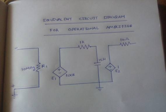
Equivalent Circuit diagram of Operational Amplifier :
Sub circuit for Opamp :
.subckt opamp 1 2 6
ri 1 2 1meg
e1 3 0 2 1 100k
r1 3 4 1k
c1 4 0 1.5u
e2 5 0 4 0 1
r0 5 6 100
.ends opamp
Non Inverting Summing Amplifier :
Subcircuit Code for NonInverting :
.subckt sum 1 2 5
.include op_gate.cir
rin1 1 3 1k
rin2 2 3 1k
x1 4 3 5 opamp
r1 4 0 1k
rf 4 5 1k
.ends sum
Logarithmic Amplifier :
Sub Circuit for Logarithmic Amplifier :
.subckt log 1 3
.include op_gate.cir
r1 1 2 100t
d1 2 3
x1 2 0 3 opamp
.ends log
AntiLogarithmic Amplifier :
Subcircuit Code for AntiLogarithmic Amplifier :
.subckt antilog 1 3
.include op_gate.cir
d1 1 2
r1 2 3 1t
x1 2 0 3 opamp
.ends
ANALOG DIVIDER CIRCUIT:
NgSpice Code :
.include op_gate.cir
.include log_gate.cir
.include antilog_gate.cir
.include sum_gate.cir
.include amp.cir
va 1 0 sin(0 4 20k)
vb 2 0 sin(0 2 20k)
x1 1 3 log
x2 2 4 log
r1 3 5 1k
rf1 5 6 1k
x3 5 0 6 opamp
x4 6 4 7 sum
x11 8 0 9 opamp
d1 7 8
rl 8 9 1
rin 9 10 1
rf0 10 11 100t
x9 10 0 11 opamp
.tran 10u 1m
.control
run
display
plot v(1)
plot v(2)
plot v(9)
.endc
.end
OUTPUT WAVEFORMS :
INPUT: (Va)
INPUT :(Vb)
OUTPUT :
CONCLUSION :
1) Analog Signal divider is done using non inverting summing amplifier , Logarithmic amplifier and antilogarithmic amplifier
2) The Subcircuit codes for every amplifier is written and executed using NGSPICE
3) The Output Waveforms are observed for every respective amplifier and are also verified.