In this circuit the duty cycle of the output square wave is not exactly 50% i.e. it is asymmetric in nature. The following figure shows such a asymmetrical square wave generator.
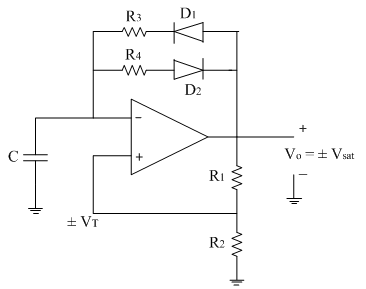
When output is high (i.e. +Vsat), diode D1 is forward biased and capacitor C starts charging through resistance R3towards +Vsat and diode D2 is reversed biased.
Therefore the charging time constant of the capacitor is τc=R3 C
When output is low (i.e. -Vsat), diode D2 is forward biased and capacitor C starts charging through resistance R3 towards –Vsat (i.e. discharging in negative direction) and diode D1 is reversed biased.
Therefore the discharging time constant of the capacitor is τd=R4 C
As in both the cases time constant is different, we get different ON and OFF time for output square wave and hence asymmetrical square wave.