Home > mini projects > Asynchronous Modulo 16 Down Counter
16 Down Counter
INTRODUCTION
Counter is a sequential circuit.A digital circuit which is used for counting pulses is known counter. Counter is the widest application of flip-flops. It is a group of flip-flops with a clock signal applied. Counters are of two types.
Asynchronous or ripple counters. Synchronous counters.
The MOD of the ripple counter or asynchronous counter is 2n if n flip-flops are used. For a 4-bit counter, the range of the count is 0000 to 1111. A counter may count up or count down or count up and down depending on the input control. The count sequence usually repeats itself. When counting up, the count sequence goes from 0000, 0001, 0010, ... 1110 , 1111 , 0000, 0001, ... etc. When counting down the count sequence goes in the opposite manner: 1111, 1110, ... 0010, 0001, 0000, 1111, 1110, ... etc.
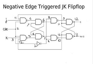
The Master-Slave D Flip Flop
The basic D-type flip flop can be improved further by adding a second SR flip-flop to its output that is activated on the complementary clock signal to produce a "Master-Slave JK-type flip flop". The inverted J input is given as K input so that the resulting flipflop is a D flipflop. On the falling edge of the clock signal (HIGH-LOW) the first stage, the "master" latches the input condition at D, while the output stage is deactivated.
On the leading edge of the clock signal (LOW-HIGH) the second "slave" stage is now activated, latching on to the output from the first master circuit. Then the output stage appears to be triggered on the negative edge of the clock pulse. "Master-Slave D-type flip flops" can be constructed by the cascading together of two latches with opposite clock phases as shown.
Using The D-type Flip Flop For Frequency Division
One main use of a D-type flip flop is as a Frequency Divider. If the Q output on a D-type flip-flop is connected directly to the D input giving the device closed loop "feedback", successive clock pulses will make the bistable "toggle" once every two clock cycles.
In the counters tutorials we saw how the Data Latch can be used as a "Binary Divider", or a "Frequency Divider" to produce a "divide-by-2" counter circuit, that is, the output has half the frequency of the clock pulses. By placing a feedback loop around the D-type flip flop another type of flip-flop circuit can be constructed called a T-type flip-flop or more commonly a T-type bistable, that can be used as a divide-by-two circuit in binary counters .
THE ASYNCHRONOUS MODULO 16
DOWN COUNTER:
WORKING OF THE COUNTER:
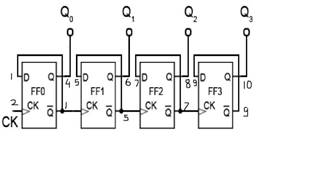
The counters in which clock is not common to all the flip flops connected in the circuit are called asynchronous counters or ripple counters.
The clock is connected to the first flip flop and output of this flip flop is given as a clock input to the next flip flop.
Thus, the next flip flop triggers at the falling edge output of the previous flip flop. The output Qbar of a particular flip flop is connected as its respective input and also as the clock input to the next flip flop.
We see the output of the flip flop as the Q output.
Here MSB is output of last flip flop and the LSB is the output of the first flip flop. The frequency is getting divided by two after passing through each flip flop.
Because of the inherent propagation delay of the flip flop, the transition of the input clock pulse and the transition of the Q output of the flip flop can never occur at the same thus introducing delay.
APPLICATIONS OF COUNTERS:
1. The counters in general can be used to measure frequency. For eg, we can use it to count line frequency.
2. As object counters.
3. In various Analog to Digital converters
4. Timers.
5. Combined with IC555 timers, long duration timers.
6. For Generating staircase voltage ( roughly similar to sawtooth waveform)
1. 3 INPUT NAND GATE *nand 3 subckt
.subckt nand3g 2 3 6 4
vdd 1 0 dc 5
.model pm pmos
.model nm nmos
mp1 4 2 1 1 pm
mp2 4 3 1 1 pm
mp3 4 6 1 1 pm
mn1 4 2 5 0 nm
mn2 5 3 7 0 nm
mn3 7 6 0 0 nm
.ends nand3g
2. 2 INPUT NAND GATE *nand 2 subckt
.subckt nand 2 3 4
vdd 1 0 dc 5
.model pm pmos
.model nm nmos
mp1 4 2 1 1 pm
mp2 4 3 1 1 pm
mn1 4 2 5 0 nm
mn2 5 3 0 0 nm
.ends nand
3. D FLIP FLOP
*jk negative edge triggered ff .subckt jk 1 2 12 11
.include nand222.sp
.include nand333.sp
x1 4 7 6 nand
x2 6 5 7 nand
x3 8 6 9 nand
x4 10 12 11 nand
x5 7 8 10 nand
x6 9 11 12 nand
x7 1 2 11 4 nand3g
x8 2 3 12 5 nand3g
x9 2 2 8 nand
x10 1 1 3 nand
.ends jk
*asynchronous
.include jksubckt1.sp
x1 1 2 4 1 jk
x2 5 1 6 5 jk
x3 7 5 8 7 jk
x4 9 7 10 9 jk
vcl 2 0 pulse(0 5 0 1p 1p 20u 40u)
.tran 1u 1000u
.control
run
display
set color0=white
set color1=black
plot v(2)
plot v(4)
plot v(6)
plot v(8)
plot v(10)
.endc
.end