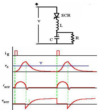
Class A: Self Commutated by a Resonating Load
Figure below shows the Class ‘A’ Commutation. When the SCR is triggered, anode current flows and charges up C with the dot as positive. The L-C-R form a second order under-damped circuit. The current through the SCR builds up and completes a half cycle. The inductor current will then attempt to flow through the SCR in the reverse direction and the SCR will be turned off. The capacitor voltage is at its peak when the SCR turns off and the capacitor discharges into the resistance in an exponential manner. The SCR is reverse-biased till the capacitor voltages returns to the level of the supply voltage V.
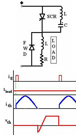
Class B: Self Commutated by an L-C Circuit
Figure below shows Class ‘B’commutation. The Capacitor C charges up in the dot as positive before a gate pulse is applied to the SCR. When SCR is triggered, the resulting current has two components. The constant load current Iload flows through R – L load. This is ensured by the large reactance in series with the load and the freewheeling diode clamping it. A sinusoidal current flows through the resonant L- C circuit to charge-up C with the dot as negative at the end of the half cycle. This current will then reverse and flow through the SCR in opposition to the load current for a small fraction of the negative swing till the total current through the SCR becomes zero. The SCR will turn off when the resonant–circuit (reverse) current is just greater than the load current. The SCR is turned off if the SCR remains reverse biased for tq>toff, and the rate of rise of the reapplied voltage < the rated value.
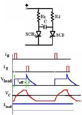
Class C: C or L-C Switched by another Load Carrying SCR
Figure below shows Class C Commutation. This configuration has two SCRs. One of them may be the main SCR and the other auxiliary. Both may be load current carrying main SCRs. The configuration may have four SCRs with the load across the capacitor, with the integral converter supplied from a current source. Assume SCR2 is conducting. C then charges up in the polarity shown. When SCR1 is triggered, C is switched across SCR2 via SCR1 and the discharge current of C opposes the flow of load current in SCR2.
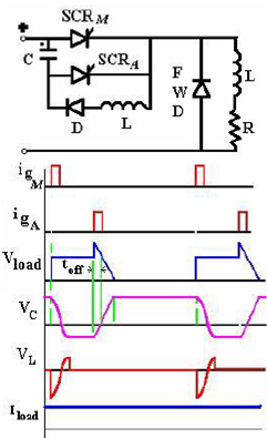
Class D: L-C or C Switched by an Auxiliary SCR
Figure below shows Class D Commutation. The circuit shown in Figure (Class C) can be converted to Class D if the load current is carried by only one of the SCR’s, the other acting as an auxiliary turn-off SCR. The auxiliary SCR would have a resistor in its anode lead of say ten times the load resistance. SCRA must be triggered first in order to charge the upper terminal of the capacitor as positive. As soon as C is charged to the supply voltage, SCRA will turn off. If there is substantial inductance in the input lines, the capacitor may charge to voltages in excess of the supply voltage. This extra voltage would discharge through the diode-inductor-load circuit. SCRA must be triggered first in order to charge the upper terminal of the capacitor as positive. As soon as C is charged to the supply voltage, SCRA will turn off. If there is substantial inductance in the input lines, the capacitor may charge to voltages in excess of the supply voltage. This extra voltage would discharge through the diode-inductor-load circuit. When SCRM is triggered the current flows in two paths: Load current flows through the load and the commutating current flows through C- SCRM -L-D network. The charge on C is reversed and held at that level by the diode D. When SCRA is re-triggered, the voltage across C appears across SCRM via SCRA and SCRM is turned off.
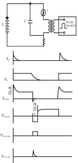
Class E: External Pulse Source for Commutation
The transformer is designed with sufficient iron and air gap so as not to saturate. It is capable of carrying the load current with a small voltage drop compared with the supply voltage. When SCR1 is triggered, current flows through the load and pulse transformer. To turn SCR1 off a positive pulse is applied to the cathode of the SCR from an external pulse generator via the pulse transformer. The capacitor C is only charged to about 1 volt and for the duration of the turn-off pulse it can be considered to have zero impedance. Thus the pulse from the transformer reverses the voltage across the SCR, and it supplies the reverse recovery current and holds the voltage negative for the required turn-off time. Figure below shows the Class E Commutation.
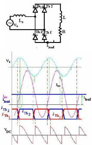
Class F: AC Line Commutated
Figure below shows the Class F Commutation. If the supply is an alternating voltage, load current will flow during the positive half cycle. With a highly inductive load, the current may remain continuous for some time till the energy trapped in the load inductance is dissipated. During the negative half cycle, therefore, the SCR will turn off when the load current becomes zero ‘naturally’. The negative polarity of the voltage appearing across the outgoing SCR turns it off if the voltage persists for the rated turn-off period of the device. The duration of the half cycle must be definitely longer than the turn-off time of the SCR.The commutation process involved here is representative of that in a three phase converter. The converter has an input inductance Ls arising manly out of the leakage reactance of the supply transformer. Initially, SCRs Th1 and Th1′ are considered to be conducting. The triggering angle for the converter is around 600. The converter is operating in the continuous conduction mode aided by the highly-inductive load. When the incoming SCRs, Th2 and Th2′ are triggered, the current through the incoming devices cannot rise instantaneously to the load current level. A circulating current Isc builds up in the short-circuited path including the supply voltage, Vs-Ls-Th1′- Th2 and Vs- Ls-Th2′-Th1 paths.