Home > mini projects > DECADE COUNTER
Abstract - In our day to day life we come across situations in which we require a system which gives us data in a specific fashion. In order to achieve such patterns, we make use of electronic circuits. In this project, a circuit has been synthesized in a way that saves a lot of board space and time required to build circuits when application demands; using a counter followed by a decoder IC.
I. INTRODUCTION
Counters are the crucial hardware components, and are defined as "The digital circuit which is used to count the number of pulses". Counters are well known to us as "Timers". Counter circuits are the best example for the flip flop applications. Counters are designed by grouping flip flops and applying a single clock signal to them. In simple words, the counters are those, which have a group of storage elements like flip flops to hold the count.
Counters have modes. The 'mod' of the counter represents the number of states of the cycles through it, before setting the counter to its initial state. For example, a binary mod 8 counter has 8 countable states. They are from 000 to 111. So, the mod 8 counter counts from 0 to 7.
A binary mod 4 counter has four count states, from 000 to
11. So, the mod 4 counter counts from 0 to 4. This means, in general a mod N counter can contain n number of flip flops, where 2n = N.
II. NEED OF COUNTERS
Counting means incrementing or decrementing the values of an operator, with respect to its previous state value. So, to perform the mathematical operations we use no devices other than counters. We cannot perform this action (counting) with any other logic devices rather than counters.
A. Types of counters:
Synchronous counters Asynchronous counters
» SYNCHRONOUS COUNTERS:
Definition: The counters which require clock signal to change their transition are called "Synchronous counters". This means the synchronous counters depends on their clock input to change state values. All flip flops in the synchronous counters are triggered by the same clock signal.
» FEATURES:
Their construction is very simple in design. All the flip flops are interconnected and will be driven by the same clock signal. The state output of the previous flip flop determines the state change of the present flip flop. As all the flip flops will work synchronously, synchronous counters don't require settling. We require a number of logic gates to implement the synchronous counters. Their operation is fast.
» ASYNCHRONOUS COUNTERS
Definition: The counters in which the change in transition doesn't depend upon the clock signal input is known as "Asynchronous counters". In these counters, the first flip flop is connected to the external clock signal, and the rest are clocked by the state outputs (Q & Q') of the previous flip flop.
» FEATURES:
Another name for Asynchronous counters is "Ripple counters". These are very simple in design.
As its design is simple, they use less number of logic gates to construct an asynchronous counter.
Operation of asynchronous counters is very slow compared to synchronous counters.
III. CIRCUIT
Below is the circuit of IC-4017 (Decade Counter)
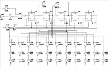
1. D-flipflops (x5): D-flipflops are cascaded to generate a decade-counter.
2. NOR Gates (x10): Output ports
3. AND Gate (x2): The output from AND gate (with clock as input) is given to D-flipflop as input clock.
4. OR Gate (x1)
5. Inverter (x1): Inverter circuit is used as one of the clock inputs CP1' and buffer is used as the other clock input.
A. D-Flipflop : Five D-flipflops are cascaded. Each flipflop has 6 pins; 4 input pins i.e. Clock, Set and Master Reset
(asynchronous), and 2 output pins i.e. Q and Q'.
When Master Reset goes high, it resets the counter to zero, independent of the clock inputs (CP0 and CP1).
B. Clock Inputs: The counter is advanced by either a low-to-high transition at one of the inputs while the other input is low or a high-to-low transition at the second input while first input is high.
When cascading counters, the Q5-9 output (see figure) can be used to drive the CP0 input of the next counter.
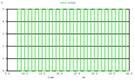
V. WAVEFORMS
Input Clock:
Output Waveforms:
Q0 Q1
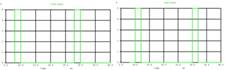
Q2 Q3
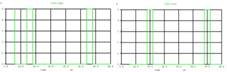
Q4 Q5
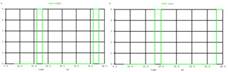
Q6 Q7

Q8 Q9

VI. CODE
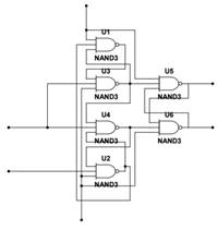
Netlist for the working of IC-4017 was simulated on NGSPICE. Sub circuits for all the Gates used were also simulated using NGSPICE software.
|
Output |
Time(us) |
|
Q0 |
8-10 |
|
Q1 |
10-12 |
|
Q2 |
12-14 |
|
Q3 |
14-16 |
|
Q4 |
16-18 |
|
Q5 |
18-20 |
|
Q6 |
20-22 |
|
Q7 |
22-24 |
|
Q8 |
24-26 |
|
Q9 |
26-28 |
VII. CONCLUSION
In this project, we have tested the code written based on the
circuit diagrams provided above. Accurate outputs are
obtained as below: