The Pulse Width Modulation (PWM) is a technique which is characterized by the generation of constant amplitude pulse by modulating the pulse duration by modulating the duty cycle. Analog PWM control requires the generation of both reference and carrier signals that are feed into the comparator and based on some logical output, the final output is generated. The reference signal is the desired signal output maybe sinusoidal or square wave, while the carrier signal is either a sawtooth or triangular wave at a frequency significantly greater than the reference.
The DC to AC power converters are known as Inverters. An inverter is a circuit which converts a dc power into an ac power at desired output voltage and frequency. The ac output voltage could be fixed or variable frequency. This conversion can be achieved either by controlled turn on and turn off devices (e.g. BJT's, MOSFETs, IGBTs, MCTs, SITs, GTOs, and SITHs) or by forced commutated thyristors, depending on applications. The output voltage waveforms of ideal inverter should be sinusoidal.
The voltage waveforms of practical inverters are, however, nonsinusoidal and contain certain harmonics. Square wave or quasi-square wave voltages are acceptable for low and medium power applications, and for high power applications low, distorted, sinusoidal waveforms are required. The output frequency of the inverter is determined by the rate at which the semiconductor devices are switched on and off by the inverter control circuitry and consequently, an adjustable frequency ac output is readily provided.
The square wave inverters need switching devices. These switching devices can either be thyristors or transistors and or other power semiconductor devices. Due to their mode of operation, losses in these semiconductor devices are very small and consequently they have a higher efficiency with much more power handling capability. There are three basic configurations of single phase square wave inverters are centre – tapped load, centre -tapped supply and bridge configuration.
By sequentially switching them on and off, the voltage across the load changes polarity cyclically and produces an alternating voltage / current. The main drawback of the centre-tapped configuration is that it needs a centre-tapped transformer/supply and higher voltage ratings transistors. This limitation can be overcome by bridge type inverters. In bridge inverters, there are four transistors for single phase operation instead of two as in centre-tapped inverters. The transistors are operated in such way that when T1 is on, T4 is off and vice-versa.
Similarly, transistors T2 and T3 are switched in a complementary manner. When transistors T1 and T2 conduct, a positive voltage appears across the load and when T3 and T4 conduct, a negative voltage is developed. If the time periods of T1 and T2 are analogous with those of T3 and T4, a square wave is produced across the load. However, if the switching of T1, T2 and T3, T4 is shifted in phase, the width of the positive and negative halves is controlled and the voltage across the load is controlled.
Pulse width modulated (PWM) inverters are among the most used power-electronic circuits in practical applications. These inverters are capable of producing ac voltages of variable magnitude as well as variable frequency. The quality of output voltage can also be greatly enhanced, when compared with those of square wave inverters. The PWM inverters are very commonly used in adjustable speed ac motor drive loads where one needs to feed the motor with variable voltage, variable frequency supply.
For wide variation in drive speed, the frequency of the applied ac voltage needs to be varied over a wide range. The applied voltage also needs to vary almost linearly with the frequency. PWM inverters can be of single phase as well as three phase types. The PWM inverters are very commonly used in adjustable speed ac motor drive loads where one needs to feed the motor with variable voltage, variable frequency supply.
For wide variation in drive speed, the frequency of the applied ac voltage needs to be varied over a wide range. The applied voltage also needs to vary almost linearly with the frequency. PWM inverters can be of single phase as well as three phase types.
Power Circuit :-
The power circuit of Single Phase Unipolar inverter consists of four bidirectional IGBT arranged in bridge form. The circuit diagram of the power circuit is shown in Figure below.
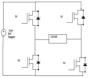
The circuit diagram consists of four distinct IGBTs such that they are connected as the bridge circuit. The input to the circuit is the 220v DC supply from the rectifier unit. The IGBTs are triggered accordingly such that the AC output voltage is obtained at the output. The operation of the circuit is as follows.
First the IGBT S1 and S4 are turned on by triggering the gate of the IGBT. During this time the input supply is 220v DC and at the output the 220v is applied across the load. The current starts from the supply positive, S1, S2, load and to the negative of the supply. The conduction path for the first cycle of operation is shown in figure below.

During the next phase or the cycle the IGBT S2 and S3 are turned on by giving trigger pulse to the gate of the IGBTs. During this period the input voltage is applied at the output but in the negative direction. The current conduction starts from the supply, S2, S3, load and to the negative of the supply. The current conduction is showed in the figure below.
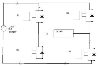
As the two cycles continue the positive and the negative voltage is applied at the load and the current direction changes in the two cycles. As the current direction changes the alternative voltage is obtained at the load thus converting DC.
Applications
- Uninterruptible Power Supply (UPS).
- Adjustable Speed Drives (ASD) for ac motors.
- Electronic frequency changer circuits used in induction heating, welding etc.
- HVDC transmission at lower power levels.
- Renewable Energy such as solar, fuel cell to AC conversion.
- Electronic Ballast and Compact Fluorescent lamps.
- Active Filters for power quality improvement.
- Custom power devices: DSTACTCOM, DVR, UPQC, FACTS: STATCOM, SSSC, UPFC, etc.
Advantages
- Low power consumption.
- High energy efficient up to 90%.
- High power handling capability.
- No temperature variation-and ageing-caused drifting or degradation in linearity.
- Easy to implement and control.
- Compatible with today’s digital microprocessors.
Disadvantages
- Attenuation of the wanted fundamental component of the waveform.
- Switching devices and therefore derating of those devices.
- Generation of high-frequency harmonic components.
- Drastically increased switching frequencies that leads to greater stresses on associated.