Home > mini projects > Analog Signals Multiplier
Analog Signals Multiplier
Abstract - In electronics , an analog multiplier is a device which takes two analog signals and produces an output which is their product. Such circuits can be used to implement related functions such as squares (apply same signal to both inputs), and square roots . An electronic analog multiplier can be called by several names, depending on the function it is used to serve
I. Introduction
Multipliers are based on fundamental logarithmic relationship that states that the product of two terms is equals the sum of the logarithms of each term. The relation is shown by the following formula ln (a»b) =ln a+ ln b. This formula shows that two signal voltages are effectively multiplied if the logarithms of the signal voltages are added.
The multiplication procedure takes three steps:
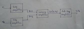
1.To get the logarithm of a signal voltage use a Log amplifier
V1»=ln(V1) and V2»=ln(V2)
2.By Summing the outputs of the two log amplifiers, you get the logarithm of the product of the two original input signals.
V0»=V1»+V2»=ln(V1)+ln(V2)=ln(V1.V2)
3.Then, by taking the antilogarithm, you get the product of the two input voltages are indicated in the following equations
V0=exp (V0») =exp [ln (V1. V2)] =V1.V2
II. Block diagram of an analog multiplier
The Block diagram shows how the functions are connected to multiply two input voltages. Constant terms are omitted for simplicity.
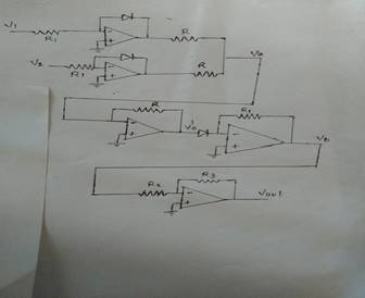
Multiplier Circuitry
III. Log and Anti-Log Amplifiers
The Log and Antilog Amplifiers are non-linear circuits in which the output voltage is proportional to the logarithm (or exponent) of the input. It is well known that some processes such as multiplication and division, can be performed by addition and subtraction of logs.
They have numerous applications in electronics, such as:
» Multiplication and division,
» Powers and roots
» Compression and Decompression
» True RMS detection
» Process control
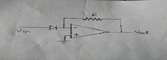
Most logarithmic amplifiers are based on the inherent logarithmic relationship between the collector current, Ic, and the base-emitter voltage, vbe, in silicon bipolar transistors.
The input voltage is converted by R1 into a. current, which then flows through the transistor's collector modulating the base-emitter voltage according to the input voltage. The opamp forces the collector voltage to that at the noninverting input, 0 V.
Log Amplifier
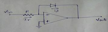
Anti-Log Amplifier
IV. Four Quadrant Multiplier
Four-Quadrant Multiplier is a device with two inputs and a output.
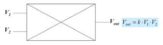
Typically, k=0.1 to reduce the possibility of overload. It is called a four-Quadrant since inputs and outputs can be positive or negative. An example is a Motorola MC1494, powered by +15 or -15V power supply.
V. Multiplier Applications
Alongside of multiplication, Multipliers are used for
» Squaring
» Dividing
» Modulation / demodulation
» Frequency and amplitude modulation
» Automatic gain control