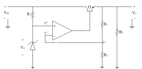
The series regulator circuit using op-amp is shown below.
The op-amp is used as a comparator. It compares the part of the output voltage obtained from potential divider circuit as a feedback with the reference voltage generated by the zener diode Vz.
The output of the op-amp drives the series pass transistor Q.
If there is any change in output voltage the control signal from op-amp control the conduction of the transistor Q. Thus the output voltage is maintained at a constant level.
From virtual ground concept
V^-=V^+
V^-=V^+=[Vo/(R1+R2 )] R2
The voltage at non-inverting terminal V+ is nothing but the zener voltage Vz as shown in figure above.
V^+=Vz
The output voltage can be expressed as
∴Vo=[(R1+R2)/R2 ] V^+
∴Vo=[(R1+R2)/R2 ] Vz
∴Vo=[1+R1/R2 ] Vz