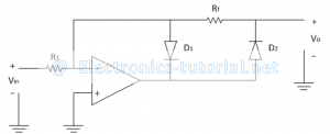
Non-saturated types of precision half wave rectifiers are suitable for high frequency applications. In HWR, the diode conducts in one of the half cycles of applied ac input signal. Because of this again we can classify HWR as positive PHWR (output is positive) and negative PHWR (output is negative). The following figure shows the circuit diagram of a positive Precision HWR.
In positive half cycle of applied ac input signal output of op-amp is negative, so diode D1 is forward biased and D2 is reversed biased. The output of op-amp is virtually shorted to ground and prevented going into saturation. Thus output voltage is zero.
∴Vo=0 V
In negative half cycle of applied ac input signal output of op-amp is positive, so diode D2 is forward biased and D1 is reversed biased. The circuit now works as an inverting amplifier with gain of(-Rf/R1 )
Therefore Vo=Vin×A
But in negative half cycle input magnitude is negative therefore we get,
Vo=(-V_in )[-Rf/R1 ]
∴Vo= Rf/R1 (Vin )
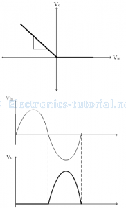
Thus in negative half cycle output is positive with a gain of(Rf/R1 ).
The transfer characteristics and input-output waveforms of Precision half-wave rectifier are shown below,

