Home > VHDL > Introduction > Data Flow Modeling
Data Flow Modeling :
The view of data as flowing through a design, from input to output. A dataflow model specifies the functionality of the entity without explicitly specifying its structure. This functionality shows the flow of information through the entity, which is expressed primarily using concurrent signal assignment statements and block statements. VHDL code is inherently concurrent (parallel). Concurrent code is also called dataflow code.
Example 1 : Two input NAND gate
  architecture DATAFLOW of NAND2 is
  begin
  X <= a nand b;
  end DATAFLOW;
In above NAND gate code is described using single concurrent signal assignment statement. A signal assignment is identified by the symbol " <=".
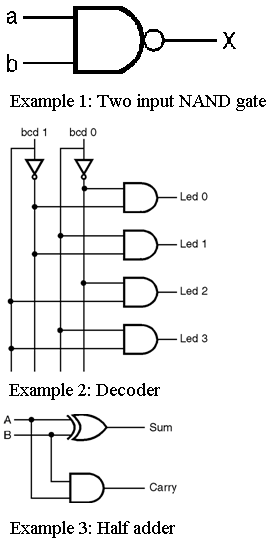
Example 2 : Decoder
  architecture Dataflow of Decoder is
  begin
  led(3) <= bcd(0) and bcd(1);
  led(2) <= bcd(0) and (not bcd(1));
  led(1) <= (not bcd(0)) and bcd(1);
  led(0) <= (not bcd(0)) and (not bcd(1));
  end Dataflow;
All the four statements here are executed concurrently and each of them is activated individually when any of its input signals changes its value.
Example 3 : Half adder
  architecture dataflow of Half-adder is
  begin
  sum <= A XOR B;
  carry <= A AND B;
  end dataflow;