Figure below shows the architecture of multiple plate capacitor in which four capacitors are fited in one architecture. In this type of capacitor two plates are connected together to form the metal plate 1 and three plates are connected together to form the metal plate 2.
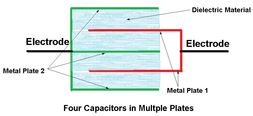
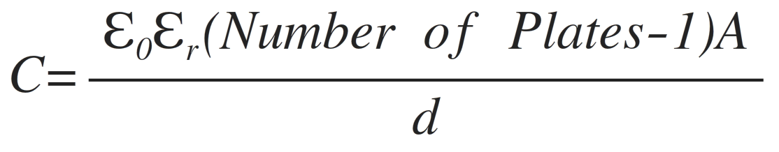
The metal plates are connected to form the elecrodes of the capacitor. In between all the plates same dielectric material used (See Figure). Therefore in this structure the four capacitors are formed in one architecture. The capacitance of this architecture is given by,
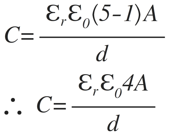
In the capacitor shown in above figure the total number of plates in the architecture are five. Hence the the surface area of the plates is only four. Hence the capacitance of the above multiple plate capacitor is given as,
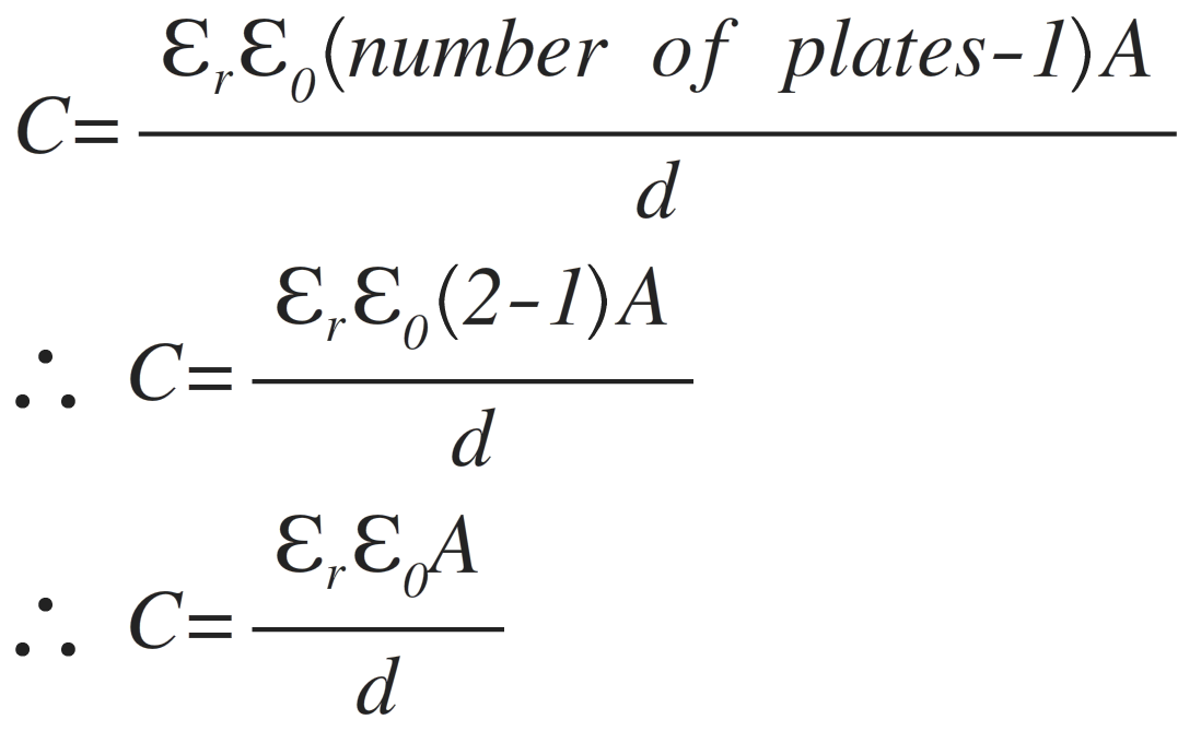
From the above analysis it can be seen that, the dielectric material increases the capacitance of the capacitance of the capacitor. The capacitance also depends upon the number of plates used in the capacitor. The material parameter which plays an important role in the capacitors is the dielectric constant of the insulator material. Further, the in the case of parallel plate capacitor the number of plates used are 2. Therefore, the capacitance is given by,
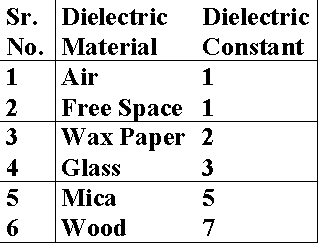
The permittivity of the dielectric is called as relative permittivity and is multiplied by the permittivity of the free space. The relative permittivity of air is equal to 1. Therefore, if air or vacuume is used as as dielectric material the εr=1. Hence, εr. ε0= 8.854×10⁻¹² F/m.
The dielectric constants of the different dielectrics are shown in below Table,