The following figure shows the configuration of op-amp as a summing integrator.
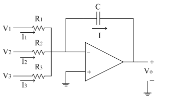
From the circuit diagram, the currents I1, I2 and I3 are added at the inverting terminal of op-amp. Since input current to the op-amp is zero, the whole current flows through the capacitor C connected in feedback path as 'I'.
The non-inverting terminal of op-amp is at ground potential. Due to virtual ground concept, the inverting terminal also appears to be at ground i. e. 0V
Thus applying KCL at inverting terminal of op-amp.
I=I1+I2+I3
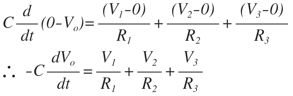
Substituting the values of currents,
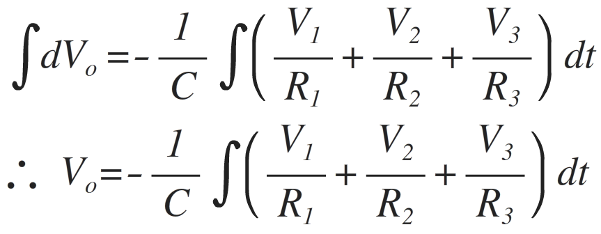
Integrating on both the sides, we get,
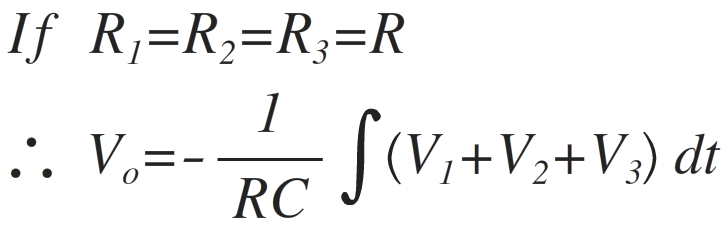
Thus the output equation gives the integration of addition of three input signals V1, V2 and V3. Thus acts as a summing integrator.