Home > finite state machines > FSM Applications > UART Receiver Design
UART-Receiver-Design
UART Receiver Design :
The UART receiver is implemented as a structural model. Some parts of it are :
10 bit counter
10 bit counter Till 10
Finite state machine
Serial to parallel converter
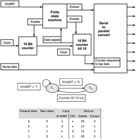
The receiver works at 16 times the frequency of transmitter. The “XmitMT†signal indicates the receiver to trigger the ten bit counter which signals at every middle of its count i.e. at 7 at which data is tapped by serial to parallel converter.The serial to parallel converter is controlled by finite state machine which has only two states. State S1 is idle and S2 is data tapping state. Output of FSM is control signal for serial to parallel converter which uses a ten bit counter which counts till ten to keep track of data and simultaneously tapping data in a 8 bit logic vector. After tapping of tenth bit the 10 bit counter (till 10) signals to FSM to switch back to state S1. The FSM is triggered from state S1 in which control signal to serial to parallel converter and enable to counter are set to '0' to state S2 on receiving “XmitMT†signal from transmitter. In state S2 all counter are enabled and serial to parallel converter is also enabled. The ten bit counter signals at every eight counts signaling that data has to be now tapped, The 10 bit counter (till 10) uses this signal as its clock to tap data. In short it is counting 10 such signals from ten bit counter.