Home > mini projects > SIMULATION OF FUNCTION GENERATOR
ABSTRACT:
A function generator is an electronic device in which various waveforms are generated and its output can be used as input to other various analog circuits. The waveforms which we tried to generate are sinusoidal , square wave and triangular waves. Any one waveform is generated first and then processing is done on it to obtain other required waveforms.
INTRODUCTION:
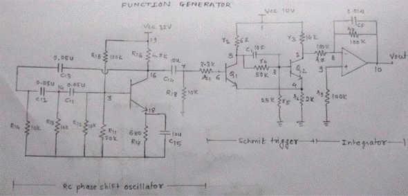
A function generator can provide different waveforms. This has an advantage over pure sine wave oscillator as function generator can also produce non-sinusoidal shapes as well.We have taken sinusoidal as the basic wave form generated with the help of "rc-phase shift oscillator". That waveform is passed through a "schmitt trigger" to obtain a square wave. An integrator follows it which gives a triangular wave. Thus the required waveforms are obtained.
RC PHASE SHIFT OSCILLATOR:
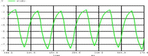
We are considering RC PHASE SHIFT by using transistors. The array resistors and capacitor values give required phase shift. The transistor gives a phase shift of 180 and hence the complete RC network to give a phase shift of 180. We have used 3 RC network, each giving a phase shift of 60.
The phase angle is given by Φ = tan-1 (Xc/R).
The values are R=10K and C=0.05u and frequency is 200Hz.
SCHMITT TRIGGER:
A schmitt trigger is a positive feedback comparator which holds the output to high as long as the input signal is greater than a reference voltage level ,otherwise it drops to zero. Usually the Schmitt trigger is designed using opamps. The difficulty faced while using opamps was that we approximated it as circuit of R,C and dependent sources. The two voltages "+Vee" and "-Vee" were not taken into account. Hence we switched to a transistor based Schmitt trigger.
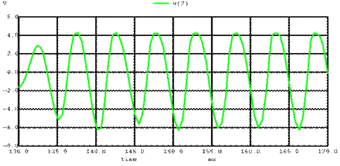
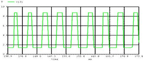
WORKING: When an input sine wave is applied, as soon as the input voltage attains a value equal to the sum of the voltages across Rb1 and Re, Q1 turns ON (saturation) and Q2 turns OFF( cut-off). Thus a square wave is produced of Vp-p of 7.3V
![]()
![]()
INTEGRATOR:
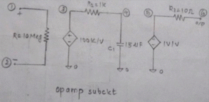
An integrator is simulated with the help of the sub circuit of an approximated opamp. An op-amp integrating circuit produces an output voltage which is proportional to the area (amplitude multiplied by time) contained under the waveform. An ideal op-amp integrator uses a capacitor connected between the output and the op-amp's inverting input terminal.
Thus the pulse waveform gets integrated and we obtain a triangular waveform. The formula used is:
![]()
CIRCUIT DIAGRAM:


![]()
![]()
MAIN CODE
![]()
![]()
![]()
![]()
*function generator*
.model bjt npn
.model bit pnp
.include opamp.cir
Q4 16 13 18 bjt
R11 13 0 20k
R12 13 0 10k
R13 14 0 10k
R14 15 0 10k
C11 13 14 0.05u
C12 14 15 0.05u
C13 15 16 0.05u
C14 16 7 10u
R15 13 19 100k
R16 16 19 4.7k
R17 18 0 680
C15 18 0 10u
R18 7 0 10k
Vcc1 19 0 dc 32V
Q1 5 6 4 bjt
Q2 2 3 4 bjt
r1 7 6 3.3k
r2 1 5 6k
r3 1 2 14k
r4 5 3 50k
r5 3 0 25k
r6 4 0 2k
r7 2 8 100k
r8 8 10 100k
r9 9 0 100k
Cf 8 10 0.01u
xop 8 9 10 opamp
c1 5 3 10f
Q3 12 11 0 bjt
r10 10 11 1k
r21 1 12 10k
vcc 1 0 dc 10
.control
tran 0.5m 500m
run
plot v(10)
plot v(2)
plot v(7)
.endc
.end
![]()
CODE:
SUB-CIRCUIT OF OP- AMP
![]()
![]()
![]()
![]()
*opamp*
.subckt opamp 1 2 6
R1 1 2 10Meg
R2 3 4 1K
R3 5 6 10
C1 4 0 15u
E1 3 0 1 2 100K
E2 5 0 4 0 1
.ends
![]()
![]()
SIMULATION:
1)SINE WAVE:

2)SQUARE WAVE:

3)TRIANGULAR WAVE:

