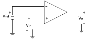
In this comparator the input voltage to be compared is applied to non-inverting terminal of op-amp. The reference voltage can be changed by connecting a potential divider arrangement as shown below.
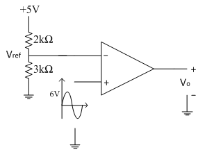
Consider the following non-inverting open loop comparator as shown below in the circuit diagram. The input applied is a sine wave of peak amplitude 6V.The reference voltage is generated from a potential divider as shown in circuit diagram below.
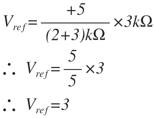
The reference voltage is calculated as
Operation:
The operation of the circuit can be explained with following two conditions
1. When Vin>Vref then Vo=+V_sat
2. When Vin<Vref then Vo=-V_sat
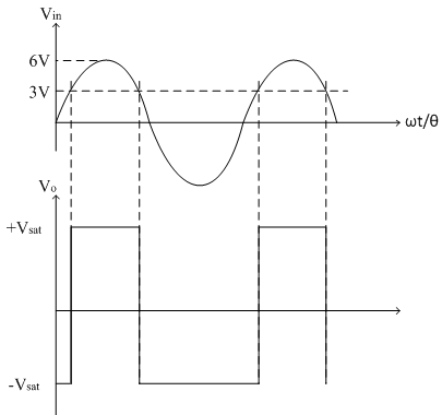
From the output waveforms shown above, input signal crosses the reference point of 3V at two points in the positive half cycle of input signal. Therefore at the two crossing points we can have the equation
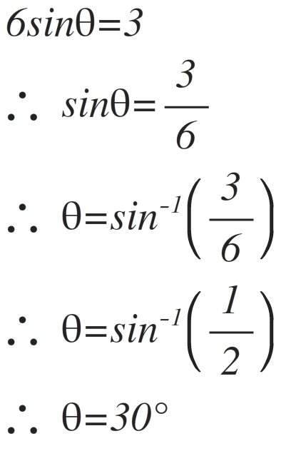
Thus at θ = 30̊, input signal crosses the reference point. Since there are two reference points in the positive half cycle of input signal and both are symmetric from both the ends. So we get two angles corresponding to two crossings as follows,
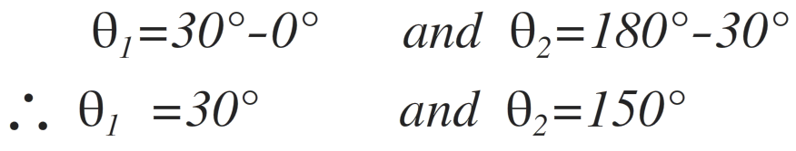
Thus between θ1 = 30̊ to θ2 = 150̊ output voltage is high (+Vsat). The complete cycle of input signal corresponds to θ = 360̊.
Thus the duty cycle of the output square wave can be represented as follows,
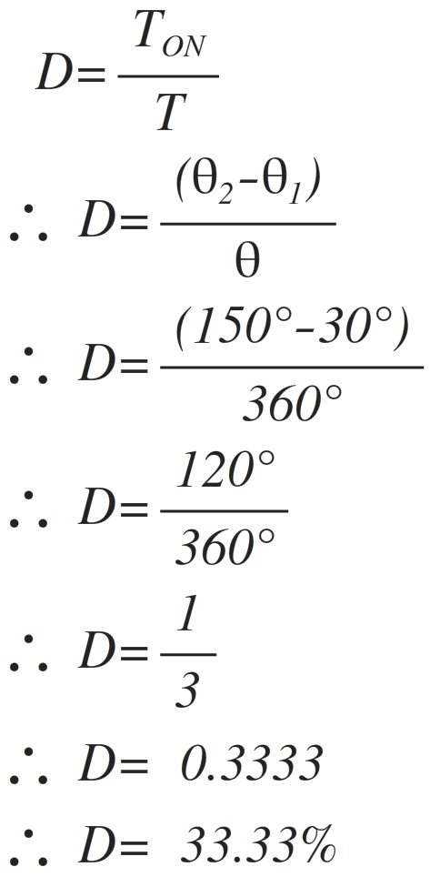
Thus the duty cycle of the output square wave is 33.33%
If now input signal is changed to have amplitude of 10V peak, the duty cycle calculations are becomes
10sinθ=3
sinθ= 3/10
∴θ= sin^(-1)(0.3)
∴θ=17.45°
So the two angles corresponding to two crossings are calculated as follows
θ1=17.45°-0° θ2=180°-17.45°
θ1=17.45° θ2=162.55°
Thus between θ1 = 17.45° to θ2 = 162.55° output voltage is high (+Vsat). The complete cycle of input signal corresponds to θ = 360̊.
Thus the duty cycle of the output square wave can be represented as follows
D= TON/T
∴D= (θ2-θ1)/θ
∴D= (162.55° -17.45°)/(360°)
∴D= (145.10°)/(360°)
∴D= 0.4030
∴D= 40.30 %
Thus the duty cycle of the output square wave is 40.30 %
Thus as the magnitude of the input signal increases, the duty cycle of the output square wave is also increases. Hence the comparator acts as a duty cycle controller.