Single Phase Full Wave Controlled Rectifier with 'R' load:
Figure below shows the Single phase Full Wave Controlled Rectifiers with R load
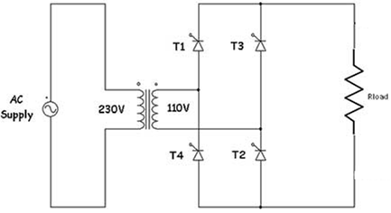
• The single phase fully controlled rectifier allows conversion of single phase AC into DC. Normally this is used in various applications such as battery charging, speed control of DC motors and front end of UPS (Uninterruptible Power Supply) and SMPS (Switched Mode Power Supply).
• All four devices used are thyristors. The turn-on instants of these devices are dependent on the firing signals that are given. Turn-off happens when the current through the device reaches zero and it is reverse biased at least for duration equal to the turn-off time of the device specified in the data sheet.
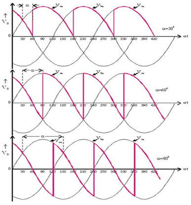
• In positive half cycle thyristors T1 & T2 are fired at an angle α .
• When T1 & T2 conducts
Vo=Vs
IO=is=Vo/R=Vs/R
• In negative half cycle of input voltage, SCR's T3 &T4 are triggered at an angle of (π+α)
• Here output current & supply current are in opposite direction
∴ is=-io
T3 & T4 becomes off at 2Ï€.
Single Phase Full Wave Controlled Rectifier with 'RL' load:
Figure below shows Single phase Full Wave Controlled Rectifiers with RL load.
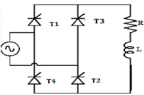
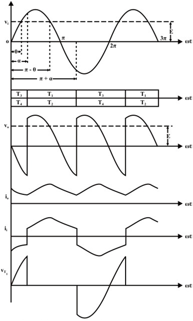
Operation of this mode can be divided between four modes
Mode 1 (α toπ)
• In positive half cycle of applied ac signal, SCR's T1 & T2 are forward bias & can be turned on at an angle α.
• Load voltage is equal to positive instantaneous ac supply voltage. The load current is positive, ripple free, constant and equal to Io.
• Due to positive polarity of load voltage & load current, load inductance will store energy.
Mode 2 (π toπ+α)
• At wt=π, input supply is equal to zero & after π it becomes negative. But inductance opposes any change through it.
• In order to maintain a constant load current & also in same direction. A self inducedemf appears across 'L' as shown.
• Due to this induced voltage, SCR's T1 & T2 are forward bais in spite the negative supply voltage.
• The load voltage is negative & equal to instantaneous ac supply voltage whereas load current is positive.
• Thus, load acts as source & stored energy in inductance is returned back to the ac supply.
Mode 3 (π+α to 2π)
• At wt=π+α SCR's T3 & T4 are turned on & T1, T2 are reversed bias.
• Thus , process of conduction is transferred from T1,T2 to T3,T4.
• Load voltage again becomes positive & energy is stored in inductor
• T3, T4 conduct in negative half cycle from (π+α) to 2π
• With positive load voltage & load current energy gets stored
Mode 4 (2π to 2π+α)
• At wt=2π, input voltage passes through zero.
• Inductive load will try to oppose any change in current if in order to maintain load current constant & in the same direction.
• Induced emf is positive & maintains conducting SCR's T3 & T4 with reverse polarity also.
• Thus VL is negative & equal to instantaneous ac supply voltage. Whereas load current continues to be positive.
• Thus load acts as source & stored energy in inductance is returned back to ac supply
• At wt=α or 2π+α, T3 & T4 are commutated and T1,T2 are turned on.