Home > Digital CMOS Design > CMOS Layout Design > Layout of logic gates
CMOS-Layout-Design
Layout of Logic gates:
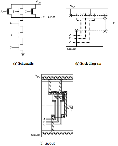
Three Input NAND Gate :
Figure below shows, the schematic, stick diagram and layout of three input NAND gate.
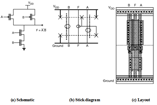
Two Input NAND Gate :
Figure below shows the schematic, stick diagram and layout of two input NAND gate implemented using complementary CMOS logic.
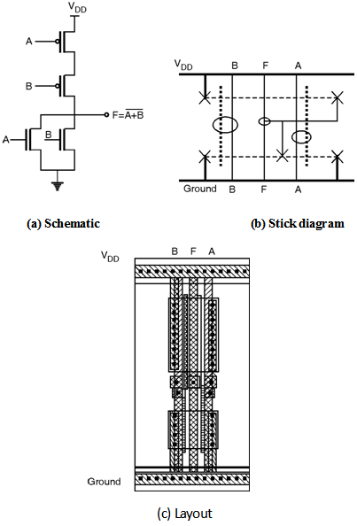
Two Input NOR Gate :
Figure below shows the schematic, stick diagram and layout of two input NOR gate implemented using complementary CMOS logic.
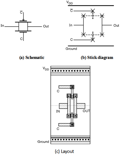
Transmission Gate :
Figure below shows the schematic, stick diagram and layout of the transmission gate.