Binary Weighted Resistor DAC
In the weighted resistor type DAC, each digital level is converted into an equivalent analog voltage or current.
The following figure shows the circuit diagram of the binary weighted resistor type DAC.
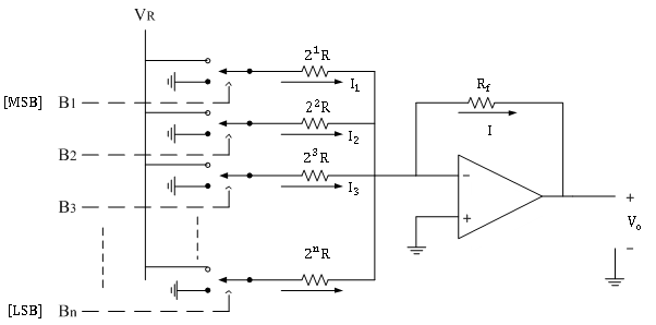
It consists of parallel binary weighted resistor bank and a feedback resistor Rf.
The switch positions decides the binary word ( i.e. B1 B2B3…Bn ).
In the circuit op-amp is used as current to voltage converter.
Analysis:
Let us analyze the circuit using normal analysis concepts used in op-amp. When the switches are closed the respective currents are flowing through resistors as shown in the circuit diagram above.
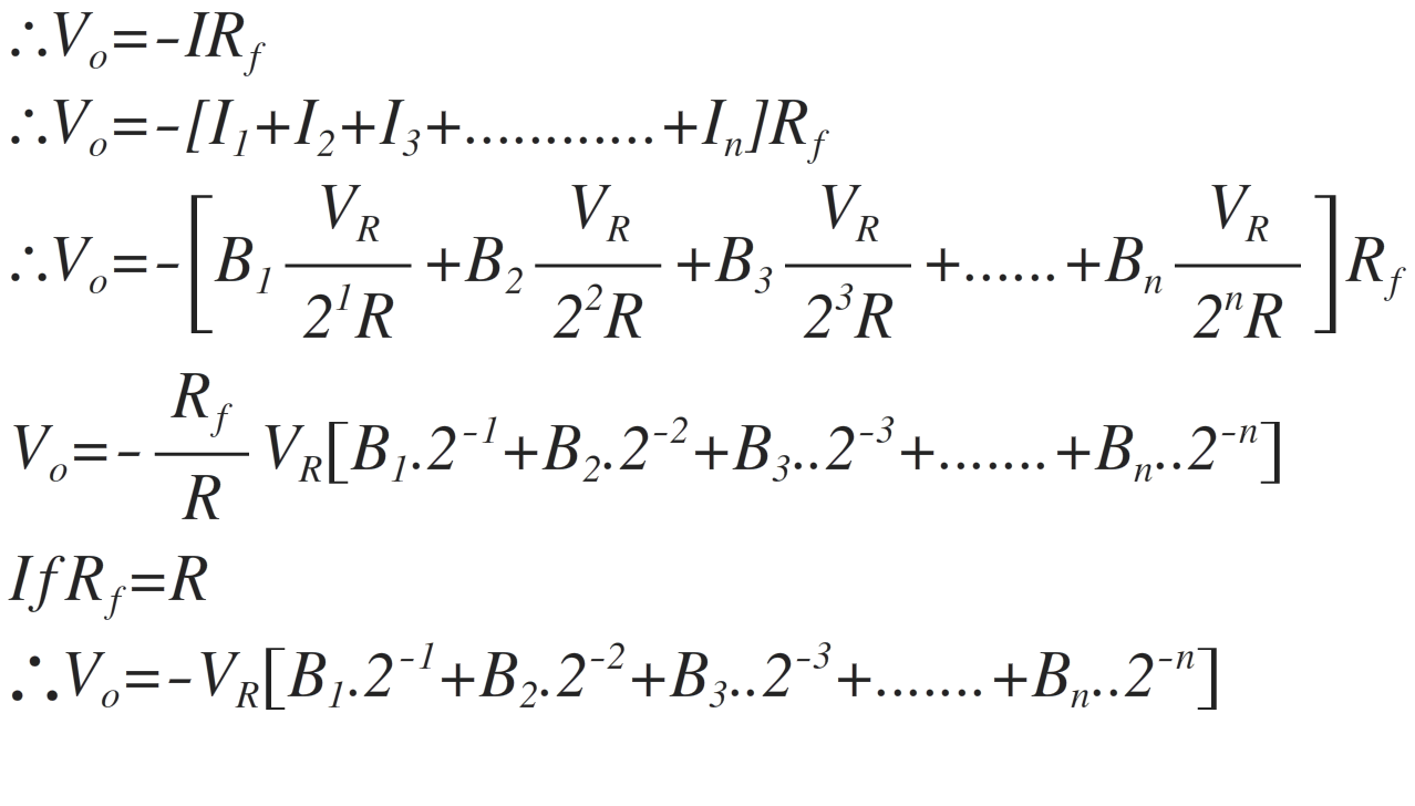
Since input current to the op-amp is zero, the addition current flows through feedback resistor.
∴I=I1+I2+I3+ …………+In
The inverting terminal of op-amp is virtually at ground potential.
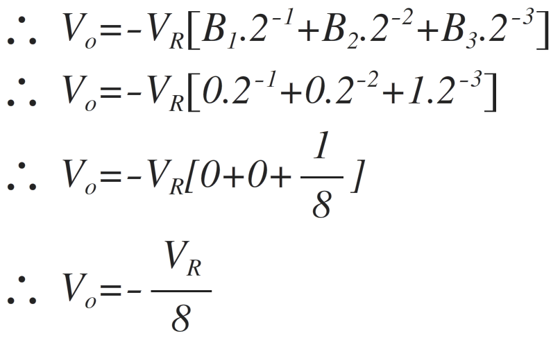
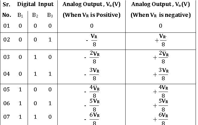
Consider the example of 3-bit DAC.
When input binary sequence is B1 B2 B3 = 001
When input binary sequence is B1 B2 B3 = 101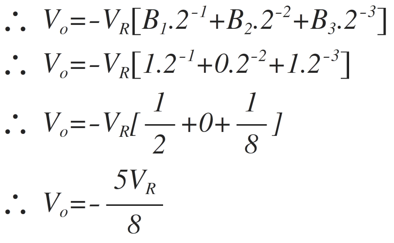
If the reference voltage is positive i.e. + VR, then the output voltage is positive.
Similarly for other six combinations of digital input, the analog output voltage Vo is calculated as follows
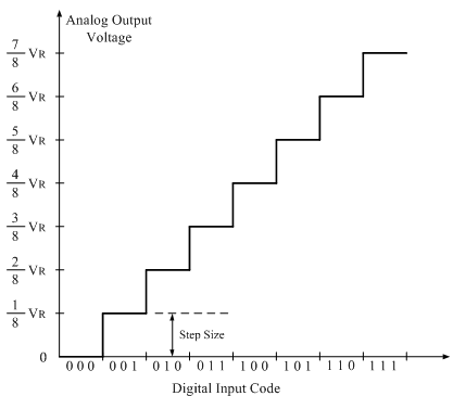
The following figure shows the staircase output voltage waveform obtained for R-2R ladder DAC (when VR is positive).
Disadvantages:
1) When number of binary input increases, it is not easy to maintain the resistance ratio.
2) Very wide ranges of different values of resistors are required.
For high accuracy of conversion, the values of resistances must be accurate.
3) Different current flows through resistors, so their wattage ratings are also different.
4) Accuracy and stability of conversion depends primarily on the absolute accuracy of the resistors and tracking of each other with temperature.
eg. For 10 digit converter
small resistance value = 10 kΩ and
large resistance value = 5.12 MΩ
It is very difficult and expensive to obtain stable precise resistances of such value.
5) Since 'R' is very large, op-amp bias currents gives a drop which offsets output.
6) Resistances of switches may be comparable with smallest resistor.