Home > finite state machines > State Machine Fundamentals > Mealy Finite State Machine
Mealy Finite State Machine
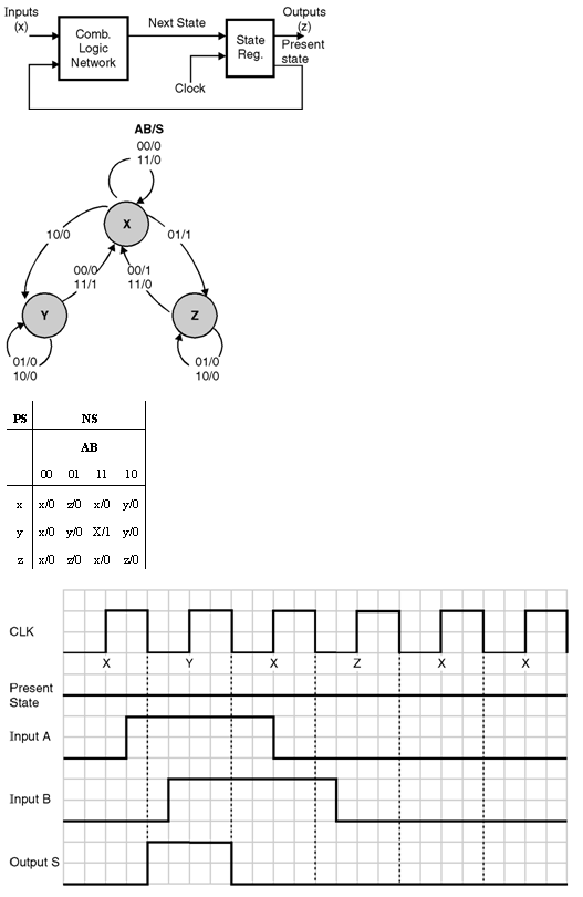
A Mealy machine is defined as a sequential network whose output is a function of both
the present state and the input to the network. The state diagram for a Mealy machine has
the output associated with the transition between states, as shown in the state diagram.
Outputs are shown on transitions since they are determined in the same way as is the next state.
In a Mealy machine, it may be possible to represent both combinations using the same state and
to compute the single bit directly from the inputs. Hence, less states. With a Mealy machine,
the outputs are computer from the state and current inputs and will not be ready for some time
after the start of the clock cycle. It is capable of generating many different patterns of output
signals for the same state, depending on the inputs present on the clock cycle.
Example of Mealy Circuit :
Circuit shown in Figure below is an example of Mealy circuit.
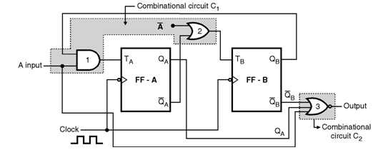
As usual, the flip flops A and B form the memory element.
Both the FFs are negative edge triggered and simultaneously clocked.
Gates 1 and 2 form the input combinational circuit C1 and gate-3 forms the output combinational
circuit. Note that the inputs to gate-3 are QA, –QB and A. That means the output is now dependent on the outputs of memory elements as well as the external input A. Also note that the changes in “A†in between the successive negative clock edges will not affect the outputs of the flip flops. But it will definitely affect the final output. This may produce a false output. To eliminate this problem, the external inputs should be allowed to change their state in synchronization with the active edge of clock.