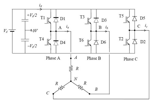
The 3-phase bridge type VSI with square wave pole voltages has been considered. The output from this inverter is to be fed to a 3-phase balanced load. Figure below shows the power circuit of the three-phase inverter. This circuit may be identified
as three single-phase half-bridge inverter circuits put across the same dc bus. The individual pole voltages of the 3-phase bridge circuit are identical to the square pole voltages output by single-phase half bridge or full bridge circuits. The three pole voltages of the 3-phase square wave inverter are shifted in time by one third of the output time period.
Voltage and Current Ratings of Inverter Switches
As in a single-phase square-wave inverter, switches in each leg of the three-phase inverter operate in a complementary manner. When upper switch of a leg is on the lower switch will need to block the entire dc bus voltage and vice versa. Thus the switches must be rated to block the worst-case instantaneous magnitude of dc bus voltage. Hence the switches must be rated to withstand the peak expected magnitude of instantaneous load-phase current. For a non-unity power factor load, the diode connected in anti-parallel with the switch will conduct part of the switch current. The distribution of current between the diode and the controlled switch will depend on the load power factor at the operating frequency. In general both diode as well as the controlled switch should be rated to carry the peak load current. These diodes also need to block a peak reverse voltage equal to worst case voltage across the switches.
Limitations of 3-Phase Square Wave Inverter:
The three-phase square wave inverter as described above can be used to generate balanced three-phase ac voltages of desired (fundamental) frequency. However harmonic voltages of 5th, 7th and other non-triplen odd multiples of fundamental frequency distort the output voltage. In many cases such distortions in output voltages may not be tolerable and it may also not be practical to use filter circuits to filter out the harmonic voltages in a satisfactory manner. In such situations the inverter discussed in this lesson will not be a suitable choice. Fortunately there are some other kinds of inverters, namely pulse width modulated (PWM) inverters, which can provide higher quality of output voltage. The square wave inverter discussed in this lesson may still be used for many loads, notably ac motor type loads. The motor loads are inductive in nature with the inherent quality to suppress the harmonic currents in the motor.
The example of a purely inductive load discussed in the previous section illustrates the effectiveness of inductive loads in blocking higher order harmonic currents. In spite of the inherent low-pass filtering property of the motor load, the load current may still contain some harmonics. These harmonic currents cause extra iron and copper losses in the motor. They also produce unwanted torque pulsations. Fortunately the torque pulsations due to harmonic currents are of high frequencies and their effect gets subdued due to the large mechanical inertia of the drive system. The motor speed hardly changes in response to these torque pulsations.
However in some cases torque pulsations of particular frequencies may cause unwanted resonance in the mechanical system of the drive. A special notch filter may then be required to remove these frequencies from the inverter output voltage. The input dc voltage to the inverter is often derived from an ac source after rectification and filtering. A simple diode bridge rectifier followed by a filter capacitor is often the most cost-effective method to get dc voltage from ac supply. In some applications, like in un-interrupted power supplies, the dc input may be coming from a bank of batteries. In both these examples, the input dc magnitude is fairly constant. With fixed input dc voltage the square-wave inverter can output only fixed magnitude of load voltage. This does not suit the requirement in many cases where the load requires a variable voltage variable frequency (VVVF) supply. In order that ac output voltage magnitude is controllable, the inverter input voltage will need to be varied using an additional dc-to-dc converter. However a better solution will be to use a PWM inverter which can provide a VVVF output with enhanced output voltage quality. In spite of the limitations, discussed above, the square wave inverter may be a preferred choice on account of its simplicity and low cost. The switch control circuit is very simple and the switching frequency is significantly lower than in PWM inverters.
This results in low switching losses. The switch cost may also be lower as one may do away with slower switching devices and slightly lower rated switches. Another advantage over PWM inverter is its ability to output higher magnitude of fundamental voltage than the maximum that can be output from a PWM inverter.
Applications of a 3-phase square wave inverter
(i) A low cost solid-state frequency changer circuit: This circuit converts the 3-phase ac (input) voltages of one frequency to 3-phase ac (output) voltages of the desired frequency. The input ac is first converted into dc and then converted back to ac of new frequency. The square wave inverter discussed in this lesson may be used for dc to ac conversion. Such a circuit may, for example, convert 3-phase ac voltages of 50 Hz to 3-phase ac voltages of 60 Hz. The input to this circuit could as well have come from a single-phase supply, in which case the single-phase ac is first converted into dc and then converted back to 3-phase ac of the desired frequency.
(ii) An uninterrupted power supply circuit: Uninterrupted power supply circuits are used to provide uninterrupted power to some critical load. Here a critical load requiring 3-phase ac supply of fixed magnitude and frequency has been considered. In case ac mains supply fails, the 3-phase load may be electronically switched, within few milliseconds, to the output of the 3-phase square wave inverter. Input dc supply of the inverter often comes from a battery bank.