Mesh analysis with independent voltage sources
Before starting the concept of mesh analysis, we want to reiterate that a closed path or a loop is drawn starting at a node and tracing a path such that we return to the original node without passing an intermediate node more than once. A mesh is a special case of a loop. A mesh is a loop that does not contain any other loops within it. The network shown in Figure has four meshes and they are identified as M_i where i = 1,2,3,4
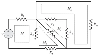
The current flowing in a mesh is defined as mesh current. As a matter of convention, the mesh currents are assumed to flow in a mesh in the clockwise Direction.
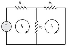
Let us consider the two mesh circuit shown in above Figure. We cannot choose the outer loop, v→R1→R2→v as one mesh, since it would contain the loop , v→R1→R3→v within it.
Let us choose two meshcurrents i1 and i2as shown in the figure.
We may employ KVL around each mesh. We will travel around each mesh in the clockwise direction and sum the voltage rises and drops encountered in that particular mesh. We will adpot a convention of taking voltage drops to be positive and voltage rises to be negative. Thus, for the network shown in Figure we have,
Mesh 1:
![]()
Mesh 2:
![]()
Note that when writing voltage across R3 in mesh 1, the current in R3 is taken as (i1 – i2 )
Note that the mesh current i1 is taken as '+ve' since we traverse in clock wise direction in mesh 1,
On the other hand, the voltage across R3 in mesh 2 is written as (i1 – i2 ) R3. The current i2 is taken as +ve since we are traversing in clockwise direction in this case too.
Solving equations of both mesh , we can find the mesh currents i1 and i2. Once the mesh currents are known, the branch currents are evaluated in terms of mesh currents and then all the branch voltages are found using Ohms's law. If we have N meshes with N mesh currents, we can obtain N independent mesh equations. This set of N equations are independent, and thus guarantees a solution for the N mesh currents.
Mesh analysis with independent current sources
Let us consider an electrical circuit source having an independent current source as shown in Figures.
We find that the second mesh current i2 = – is and thus we need only to determine the first mesh current i1,
Applying KVL to the first mesh, we obtain
(R1+R2 ) i1 – R2 i2 = v
Since i2 = – is
We get (R1 + R2 ) i1 – R2 is = v
i1=(v – R2 is)/(R1 + R2 )

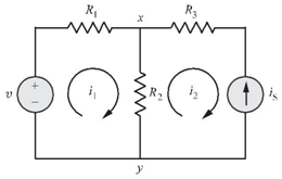
As a second example, let us take an electrical circuit shown in figure in which the current source is is common to both the meshes. This situation is shown in Figure above.
By applying KCL at node x, we recognize that
i1 – i2 = is
The two mesh equations (using KVL) are
Mesh 1: R1 i1 + vxy – v = 0
Mesh 2: (R2 + R3 ) i2 – vxy = 0
Adding the above two equations,
we get
R1 i1 + (R2 + R3 ) i2 = v
Put
i2 = is + i1
R1 i1 + (R2 + R3 )(is + i1 ) = v
∴i1 = (v – (R2 + R3 ) is) / (R1 + R2 + R3 )
In this manner, we can handle independent current sources by recording the relationship between the mesh currents and the current source. The equation relating the mesh current and the current source is recorded as the constraint equation.
Step wise procedure for mesh analysis :
Follow the step wise procedure given below to practically apply the Kirchhoff’s laws :
Step 1 :Draw the correct circuit diagram and name all the junctions (nodes), as A, B, C ….. etc.
Step 2 :Mark all the possible branch currents or loop currents with some assumed directions. Note that the assumed current may be correct or may be wrong. If an assumed current direction is correct, then in the answer it comes out to be positive. Otherwise it will be negative.
Step 3 :Mark these currents using KCL so as to minimize the number of unknown currents. At node A the current I1 gets divided into two currents. Mark them as I2 and (I1 – I2) and not as I2 and I3.
Step 4 :Then apply KVL to the various closed paths and write the corresponding simultaneous equations. Remember that all the circuit elements given in the example must be used at least once. Convert these equations into the matrix form.
Step 5 :Solve these simultaneous equations and obtain the magnitude and directions of all the unknown currents.
Step 6 :We can then use these unknown current for the calculations of unknown voltages, power consumed by various components.
Mesh analysis for the circuits involving dependent sources
The presence of one or more dependent sources merely requires each of these source quantities and the variable on which it depends to be expressed in terms of assigned mesh currents. That is, to begin with, we treat the dependent source as though it were an independent source while writing the KVL equations. Then we write the controlling equation for the dependent source.
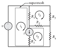
Supermesh
A more general technique for mesh analysis method,when a current source is common to two meshes,involves the concept of a supermesh. A supermesh is created from two meshes that have a current source as a common element; the current source is in the interior of a supermesh. We thus reduce the number of meshes by one for each current source present. Figure shows a supermesh created from the two meshes that have a current source in common.