Home > Analog CMOS Design > Signal Conditioning > DAC Circuits
Digital to Analog Converter Circuits :
Figure below shows a simple circuit for a N bit D/A converter. The circuit consists of a reference voltage VREF, N binary weighted resistors R, 2R, 4R, 8R, … 2(N-1) R, N single pole double throw switches S1, S2, S 3… SN, and a op-amp along with its feedback resistance Rf = . The switches are controlled by a N bit digital input word.
i.e. Data = + + … +
Where b1, b2 and bN are bit coefficients that are either 1 or 0. Here bN is the least significant bit (LSB) and b1 is the most significant bit (MSB).
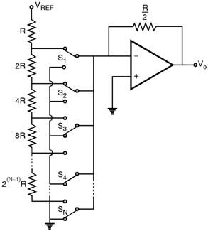
As one of the position of each switch is ground and because of virtual ground concept of op-amp the current through each resistor is constant. The current flowing into virtual ground add up and the sum flows through the feedback resistance Rf. The total current io is given by,
io = b1 + b2 + … + × b N
=
Hence io = (Data)
and the output voltage is given by,
Vo = - io Rf = - VREF (Data)
The switches in the circuit can be implemented with the MOSFETs and any of
the
op-amp topology discussed in the previous section can be used to implement
the circuit. A disadvantage of the binary weighted resistor network is that
for a large number of bits
(i.e. N > 4) the spread between the smallest and largest resistances
becomes quite large. This implies difficulties in maintaining accuracy in
resistor values. A more convenient scheme is using R-2R ladder network.
Figure below shows the basic arrangement of a D/A converter using an R-2R ladder. Because of the small spread in resistance values this network is usually preferred to the binary weighted scheme. Operation of R-2R ladder is straight forward.
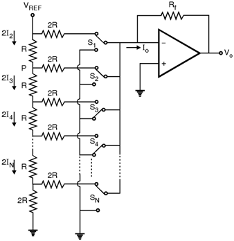
It can be shown that by starting from top and working toward the down the resistance to the right of each ladder node such as labelled 'P' is equal to 2R. Thus the current flowing in the down direction of each node is equal to the current flowing right to ground and twice that current flows into the node from top.
It gives, I1 = 2 I2 = 4 I3 = … = 2 N - 1 N
Thus as in the binary weighted resistive network the currents controlled by switches are binary weighted. The output current Io is given by,
Io = (Data)