Home > System On Chip > Interconnects > RC Wire Model
RC-Wire Model
The signal propagation in wire includes :
1) the distributed resistance and capacitance of the wire,
2) the impedance of the driving source, and
3) the load impedance.
Due to high resistance very long wires the transmission line effect larger. The wire is expressed by the several RC sections, as shown in figure. The response at node is represented by, C dVjdt – (Ij – 1 – Ij) – (Vj – 1 – Vj)R – (Vj – Vj + 1)R
Further, when the sections are increased, it is expressed as,
rc dVdt = d2Vdx2 where x = Distance from input r = Resistance per unit length c = Capacitance per unit length
Solution of this differential form yields an approximate signal delay of :
tl = rcl22 where r = Resistance per unit length c = Capacitance per unit length l = Length of the wire
Here l2 shows the delay is larger by RC effect for very long wires. In m order to improve the speed the line is segmented into various sections and buffers are inserted in the sections as shown in figure. Further, the simple model is shown in figure, here, Rs is the output resistance. Cl is the receiver input capacitance. Rt and Ct are the total lumped resistance and capacitance of the wire. is the RC delay.
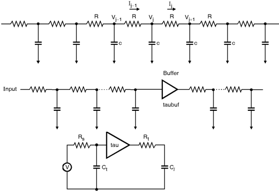
Fig_RC-Wire Model