Introduction to Amplifiers
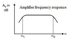
In the analog circuits the transducers provide signals that are weak in amplitude in the range of microV or mV and possesses very less energy. This type of signals are too small for reliable processing. So it is necessary to enhance the amplitude of such weak signals. The functional block that does this task is called as the signal amplifier. The amplifier discussed previously is called as the voltage amplifier since its purpose is to increase the voltage level of the signal. The parameters that we are primarily interested in the amplifiers are the ac small signal, mid-band voltage/current gains and the input/output resistances. In general, the gain of amplifier, if plotted as a function of frequency shows an inverted bathtub type of characteristics, i.e. the gain falls at very low as well as very high frequencies as shown in below figure. In between these two extremes there is range of frequencies over which the gain maintains a constant value and thus is independent of the frequency, this range is known as mid-band range or simply mid-band.
Below figure shows the magnitude response of the amplifier it indicates that the gain is almost constant over a wide range in between w1 and w2. The signals whose frequencies are below w1 or above w2 will have lower gain.
CLASSIFICATION OF AMPLIFIERS
Most electronic devices used at least one amplifier, but there are many types of amplifiers.
Instrumentation Amplifier, Operational Amplifier, voltage amplifiers etc.
This module will not try to describe all the different types of amplifiers.
You will be show some typically amplifier circuits and general principles of amplifiers.
Generally amplifiers can be classified in 2 ways.
The first classification is by their function. This means they are basically
a) Voltage amplifiers
b) Power amplifiers
The band of frequencies over which the gain of the amplifier is almost constant within 3 dB range is called as the amplifier bandwidth (mid-band).
There are four types of amplifiers used in analog integrated circuits that are :
1) Voltage amplifier
2) Current amplifier
3) Transresistance amplifier
4) Transconductance amplifier.
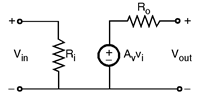
- Voltage Amplifier
The voltage amplifier takes the small input voltage signal and raises its amplitude by a factor called as the gain of amplifier. The voltage gain of the voltage amplifier is,
The input impedance Ri = ∞ and the output impedance Ro = 0. Fig. Voltage amplifier
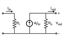
2)Current Amplifier :
The current amplifier takes the input as a small
current and raises the magnitude of current at output.
Below Figure shows the ideal model of the current amplifier.
The current gain of the current amplifier is, Alpha [Latex]i=\frac { Iout }{ Iin }[/Latex]
The input impedance Ri = 0 and the output impedance Ro = ∞. Fig. Current amplifier.
3) Transresistance Amplifier :
The transresistance amplifier takes the input as the small current and raises the voltage
levels at the output node. Below figure shows the Ideal model of transresistance amplifier.
Av =
Ai =
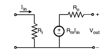
Figure Transresistance amplifier
The transresistance of the amplifier is given as,
The input impedance Ri = 0 and the output impedance Ro = 0.
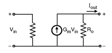
4) Transconductance Amplifier :
The transconductance amplifier takes the input
as the voltage and raises the current at the output node.
Rm =
Questions
Q-1. What is amplification?
Q-2. Does an amplifier actually change an input signal? Why or why not?
Q-3. Why do electronic devices use amplifiers?
Q-4. What are the important parameters of an amplifier?
Q-5. What are the types of amplifiers used in analog integrated circuits ?
Users Also read
- Instrumentation Amplifier
- Inverting amplifier
- Isolation Amplifier
- Non-inverting amplifier
- Operational Amplifier
- Unity gain Buffer
Amplifier Quiz
Op-Amp Quiz