Servomotor is a Specialized motor that can move their shaft to a specific position Built from DC motor by adding: Gear reduction Position sensor for motor shaft Control circuit that tell motor how much to turn and in what direction. A servomotor (servo) is an electromechanical device in which an electrical input determines the position of the armature of a motor. Servos are used extensively in robotics and radio-controlled cars, airplanes, and boats.
Servomotors are used in feedback control systems. Servomotors have low rotor inertia and high speed of response. The servomotors are also known as a control motors. The servomotors which are used in feedback control system should have linear relationship between electrical control signal and rotor speed, torque speed characteristics should be linear, the response of the servomotor should be fast and inertia should be low.
Servo motors are also called control motors and have high-torque capabilities. Servo motors are not used for continuous energy conversion but only for precise speed and precise position control at high torques. Of course, their basic principle of operation is the same as that of other electromagnetic motors. However, their construction, design and mode of operation are different. Their power ratings vary from a fraction of a watt up to a few 100 W. Due to their low-inertia, they have high speed of response. That is why they are smaller in diameter but longer in length. They generally operate at very low speeds or sometimes zero speed. They find wide applications in radar, tracking and guidance systems, process controllers, computers and machine tools. Both dc and a. c. (2-phase and 3-phase) servomotors are used at present.
Types of servomotor :
a) A. C. Servomotor
b) D. C. Servomotor
i) armature controlled d. c servomotors
ii) Field controlled d. c servomotor.
AC Servomotor:
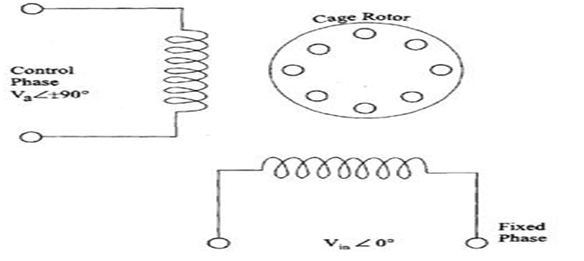
These motors having two parts namely stator and rotor. AC servomotors are two phase induction motor. The stator has two distributed windings. These windings are displaced from each other by 90 electrical. One winding is called as a main winding or reference winding. The reference winding is excited by variable control voltage of the same frequency as a reference winding but having a phase displacement of 90 electrical. The variable control voltage for control winding is obtained from a servo amplifier. The direction of rotation of the rotor can be reversed by reversing the phase difference between control voltage and reference voltage.
The rotors of a. c servomotors are of two types
1) Squirrel cage rotor
2) Drag cup type rotor.
The squirrel cage rotor having a large length and a small diameter, so its resistance is very high. The air gap of squirrel cage is kept small. In drag cup type there are two air gaps.
For the rotor a cup of non magnetic conducting material is used. A stationary iron core is placed between the conducting cups to complete the magnetic circuit. The resistance of drag cup type is high and therefore having a high starting torque. Generally aluminum is used for cup. Figure below shows the schematic of AC servomotor.
D.C Servomotor
D.C Servomotors are separately excited or permanent magnet d. c servomotors. The armature of D.C servomotor has a large resistance therefore a torque speed characteristic is linear. The D.C servomotors can be controlled from armature side or from field. In field controlled D.C servomotors the ratio of L/R is large. i.e. time constant for field circuit is large. Due to large time constant, the response is slow and therefore they are not commonly used. The speed of motor can be controlled by adjusting the voltage applied to the armature. In armature controlled DC servomotor the time constant is small and hence the response is fast. The efficiency is better than field controlled motor.
These motors are either separately-excited dc motors or permanent-magnet dc motors. The schematic diagram of a separately-excited dc motor is shown in Fig. The speed of d.c. servomotors is normally controlled by varying the armature voltage. Their armature is deliberately designed to have large resistance so that torque-speed characteristics are linear and have a large negative slope. The negative slope serves the purpose of providing the viscous damping for the servo drive system.
