The PLL IC 565 is usable over the frequency range 0.1 Hz to 500 kHz. It has highly stable centre frequency and is able to achieve a very linear FM detection. The output of VCO is capable of producing TTL compatible square wave. The dual supply is in the range of ±6V to ±12V. The IC can also be operated from single supply in the range 12V to 24V.
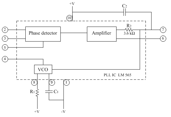
The following figure shows the pin-out and the internal block schematic of PLL IC LM 565.
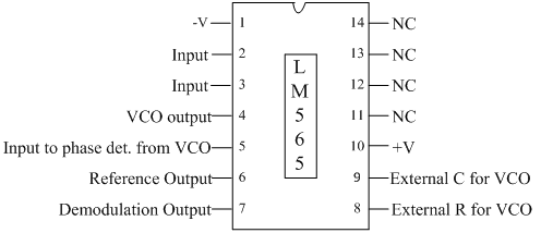
It is a 14 pin IC, operated from a dual power supply +V (at pin no. 10) and –V (at pin no. 1).
Pin no 2 & 3 -> Signal input for phase detector.
Pin no 4 ->VCO output is available
Pin no 4 & 5 are shorted externally so that VCO output is applied for phase detection. In some applications PLL loop is broken and some circuit is to be connected between pin no 4 and 5.
Pin no 6-> reference dc voltage is available.
Pin no 7 -> demodulated output.If input signal between pin no 2 and 3 is FM signal then at pin no 7 we get FM demodulation output.
Pin no 8 and 9 -> external R1 and C1 for VCO (determines free running frequency of VCO)
Internal resistance R2 and external capacitor C2 forms a LPF. The value of internal resistance R2 is 3.6kΩ.
Features of IC 565:
1) Extreme stability of center frequency typically 200ppm.
2) Wide range of operating voltage ±6V to ±12V.
3) Very high linearity of demodulated output typically 0.2%
4) Centre frequency of VCO is programmable by means of resistor, capacitor or voltage.
5) TTL compatible square wave output.
6) Highly linear triangular wave output available at pin no.9
7) Loop can be broken between pin no.4 and 5 and external circuit can be added.
8) Frequency adjustable over the range 1:10 with single capacitor.
Design Equations:
1. Centre Frequency (Free running freq./ output freq./oscillator freq.)
fo=0.3/(R1 C1 )
2. Lock range
fL=(8fo)/V
where V=|+V|+|-V|……..(addition of two power supplies)
3. Capture range
fc=±1/2π √((2πf_L)/(R_2 C_2 ))