In this circuit input is applied to the non-inverting terminal of op-amp. Inverting terminal is kept at reference potential. In this case the reference voltage is zero. i.e. Vref = 0V. Figure below shows the Non-Inverting Comparator.
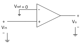
The op-amp is in open loop configuration and hence its output is in saturation. The saturation level at the output may be positive or negative depending on the input signal. Here op-amp acts as a comparator and compares the input signal with the reference voltage.
If the difference between the two signals is positive, op-amp goes into positive saturation i.e. Vo = +Vsat .
If the difference between the two signals is negative, op-amp goes into negative saturation i.e. Vo= -Vsat.
The above simple operation can be summarized in mathematical conditions as follows.
1. If Vin>Vref, Vo = +Vsat
2. If Vin<Vref, Vo = -Vsat
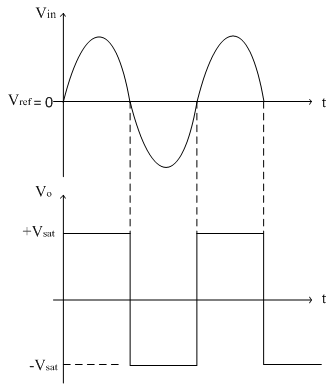
The input and output waveforms are shown below,
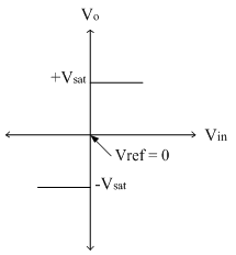
The transfer characteristics are shown below,