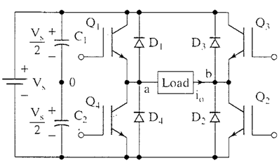
A single phase bridge DC-AC inverter is shown in Figure below. The analysis of the single phase DC-AC inverters is done taking into account following assumptions and conventions.
1) The current entering node a in Figure 8 is considered to be positive.
2) The switches S1, S2, S3 and S4 are unidirectional, i.e. they conduct current in one direction.
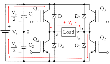
When the switches S1 and S2 are turned on simultaneously for a duration 0 ≤ t ≤ T1 , the the input voltage Vin appears across the load and the current flows from point a to b.
Q1 – Q2 ON, Q3 – Q4 OFF ==> ν o = Vs
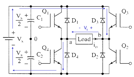
If the switches S3 and S4 turned on duration T1 ≤ t ≤ T2, the voltage across the load the load is reversed and the current through the load flows from point b to a.
Q1 – Q2 OFF, Q3 – Q4 ON ==> ν o = -Vs
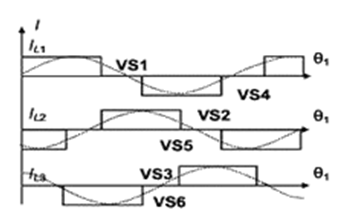
The voltage and current waveforms across the resistive load are shown in Figure below.
Single Phase Full Bridge Inverter for R-L load:
A single-phase square wave type voltage source inverter produces square shaped output voltage for a single-phase load. Such inverters have very simple control logic and the power switches need to operate at much lower frequencies compared to switches in some other types of inverters. The first generation inverters, using thyristor switches, were almost invariably square wave inverters because thyristor switches could be switched on and off only a few hundred times in a second. In contrast, the present day switches like IGBTs are much faster and used at switching frequencies of several kilohertz. Single-phase inverters mostly use half bridge or full bridge topologies. Power circuits of these topologies are shown in in Figure below.
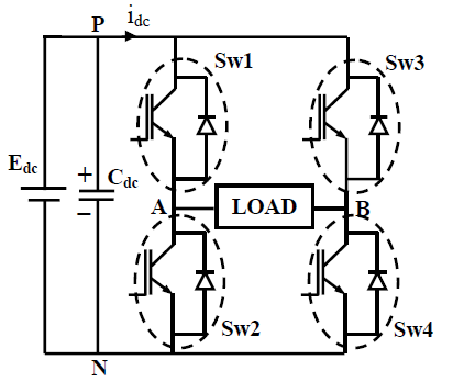
The above topology are analyzed under the assumption of ideal circuit conditions. Accordingly, it is assumed that the input dc voltage (Edc) is constant and the switches are lossless. In full bridge topology has two such legs. Each leg of the inverter consists of two series connected electronic switches shown within dotted lines in the figures. Each of these switches consists of an IGBT type controlled switch across which an uncontrolled diode is put in anti-parallel manner. These switches are capable of conducting bi-directional current but they need to block only one polarity of voltage. The junction point of the switches in each leg of the inverter serves as one output point for the load.