Home > mini projects > ASK Modulation using OPAMP
ASK Modulation using OPAMP
Abstract: Amplitude Shift Keying plays a major role in the field of digital modulation because of its simplicity in implementation as well as detection. ASK involves multiplier circuit with data stream and a high frequency carrier signal as input. The resulting ASK modulated output signal is highly band efficient.
I. INTRODUCTION1
In the world of electronics and telecommunications, modulation implies variation in some parameter of the carrier signal by means of the signal that is to be transmitted. In earlier days, communication was mostly achieved using analog domain .However, there were many drawbacks in this case. With the advent advancement in research, digital domain was proven to be far more efficient over analog.
The baseband signal cannot be transmitted over long distances because of its low frequency. Consequently, this baseband signal has to be modulated in order to shift its frequency to RF range. Among various available modulation techniques, ASK is the simplest modulation technique being discussed here.
II. CIRCUIT IMPLEMENTATION A. Operational Amplifier
An Operational Amplifier, or op-amp for short is basically a voltage amplifying device with 2 terminals as input and one terminal as output. It requires external feedback to control its overall response characteristics or operation. Differential amplifier is the basic building block of op-amp. The differential amplifier stage is followed by a level translator and then an output stage.
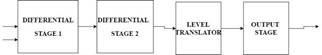
Op-amp has infinite input impedence resulting in no current flowing in either of its input terminals and zero input offset voltage. Further it has zero output resistance. It is a three terminal device having two input terminals: Inverting terminal (-) and Non-Inverting terminal (+) and an
![]()
output terminal. The difference of the voltages applied at input terminals is amplified by gain value. It can work as an ideal amplifier with infinite gain and bandwidth when used in the open -loop mode.
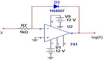
B. Logarithmic Amplifier
An operational amplifier can function as a logarithmic amplifier in which output of the op-amp is log of the input. It is said to be configured in non-linear mode. In this circuit, a diode is placed in the feedback path of op-amp. When the diode is forward biased by a constant current of magnitude Vi/R, it develops a potential:
![]()
Where Vd is potential across diode
Vt is thermal voltage
R is resistance at inverting terminal
Io is saturation current
Vi is input voltage
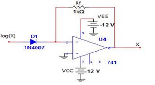
C. Anti-Logarithmic Amplifier
An operational amplifier can function as an anti-logarithmic amplifier in which output of the op-amp is anti-log of the input. It is said to be configured in non-linear mode. In this circuit, a diode is placed at the inverting terminal input and a diode in the feedback network. When the diode is forward biased by a constant current of magnitude Vi/R, it develops a potential:
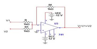
D. Summing Amplifier
The op-amp amplifies each input voltage by gain value and produces an algebraic sum of these inputs at the output terminal. In case Inverting Summing Amplifier, the output is
Vout = - ( )
![]()
Where v1, v2, v3 are three input voltages to be summed
up
Rf is feedback resistance
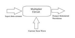
E. Multiplier Circuit
Here the multiplier circuit is implemented using Log, anti-log and summing amplifier circuits discussed previously.
F. ASK modulator:
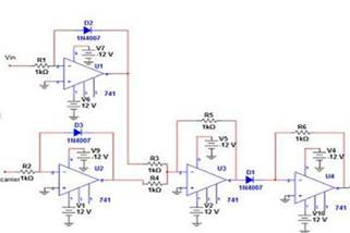
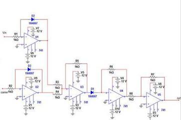
The ASK modulator is implemented using the multiplier circuit discussed above. To one of the log amplifiers data stream is given as input and to the other the high frequency carrier is given as input. The output of multiplier circuit is given to an inverting amplifier as in the multiplier stage op-amp is used in inverting configuration.
CIRCUIT DIAGRAM:
NGSPICE NETLIST FOR ASK MODULATOR:
Op-amp subcircuit:
.subckt opamp 1 2 6
E1 3 0 2 1 100k
E2 5 0 4 0 1
R1 1 2 100meg
r2 3 4 1k
r3 5 6 10k
c1 4 0 1.6u
.ends opamp
ASK modulator:
*mod
.include op.cir
v1 1 0 sin(0 10 20k)
v2 2 0 pulse(0 10 0 0 0 1ms 2ms)
r1 1 3 1k
r2 2 4 1k
x1 3 0 5 opamp
x2 4 0 6 opamp
d2 3 5
d3 4 6
r3 5 7 1k
r4 6 7 1k
x3 7 0 8 opamp
r5 7 8 1k
d1 8 10
x4 10 0 11 opamp
r6 10 11 1k
x5 12 0 13 opamp
r7 11 12 1k
r8 12 13 10k
.tran 1u 10ms
.control
run
display
set color0=white
set color1=black
set xbrushwidth=3
plot v(1)
plot v(2)
plot v(13)
.endc
.end
Input Waveforms:
a) Carrier wave:
b) Data to be modulated:
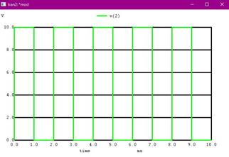
3
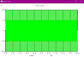
Output:
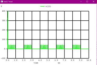
III. CONCLUSION
ASK modulation has been implemented using NGSPICE simulator. The multiplier circuit implemented using op-amp Generated the desired results in accordance to the input data stream and carrier.
ASK is widely accepted due to its simplicity in implementation as well as detection. It requires lesser bandwidth when compared to FSK.
However it is more prone to noise leading to usage only in more noise immune channels like Optical fibres.