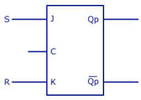
This will be the reverse process of the earlier explained conversion. S and R will be the external inputs to J and K. As shown in the logic diagram below, J and K will be the outputs of the combinational circuit. Thus, the values of J and K have to be obtained in terms of S, R and Qp. The logic diagram is shown below.
A conversion table is to be written using S, R, Qp, Qp+1, J and K. For two inputs, S and R, eight combinations are made. For each combination, the corresponding Qp+1 outputs are found ut. The outputs for the combinations of S=1 and R=1 are not permitted for an SR flip flop. Thus the outputs are considered invalid and the J and K values are taken as “don’t cares”.