Home > mini projects > IC 555 timer as an Audio Amplifier
Abstract-Simulation of IC555 timer used as an audio amplifier is done in NgSpice.The amplifying of input electrical signal and its Pulse Width Modulation by Timer 555 is done which produces a carrier frequency suitable for modulation with input audio signal which will drive the Speaker.The input for simulation purpose is given a sine wave and resultant obtained wave is a square wave with varying width according to amplitude.This wave drives the speaker in Practical Application.
I. INTRODUCTION
In this project we are describing the principle, design and operation of a low power audio amplifier using 555timer.This 555 timer generates a carrier signal which is modulated by the amplified audio signal to produce a modulated signal. This signal is used to drive a small loudspeaker.
A. NgSpice
Simulator Software used is Ngspice.It implements three
classes of analysis-
1.Linear AC
2.Non Linear DC
3.Non Linear transient.
It supports parametric netlists.It is a code based simulator whose circuits are only described as text and not capable of drawing symbols.// Usually Notepad++ is accompanied where all codes are written and then run on ngspice.exe
B. Principle
Microphone converts input audio signal to electrical signal.This electrical signal is amplified on which Pulse width Modulation is done using IC 555.The output wave drives the speakers which are basically transducers which convert input electrical signal wave into an audio signal.
II. COMPONENTS:
A. IC 555
A standard 555 package includes-
1.A silicon chip
2. 2 Diodes
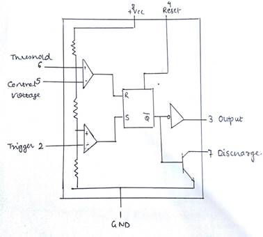
Fig. 1. Ic 555 Internal
3. 25 Transistors
The internal block diagram is shown in th figure-It consists of-
1.A voltage divider consisting of three identical resistors between Vcc and GND
2.A comparator with reference 2/3Vcc obtained by voltage divider
3.A comparator with refernce 1/3Vcc obtained by voltage divider
4.A R-S flip flop which stores state of timer
5.A discharge transistor.
1) Astable Multivibrator Overview: Earlier Capacitor is discharged thus output goes HIGH.Now Capacitor starts charging from +Vcc by a discharge transistor.It charges till it reaches +2Vcc/3 after which discharge transistor turns ON and output enter LOW state.
 It will again start charging after reaching +Vcc/3 Thus acts as a free
running multivibrator.HIGH state time period is governed by +Vcc/3 to
+2Vcc/3 and discharge by +2Vcc/3 to +Vcc/3
It will again start charging after reaching +Vcc/3 Thus acts as a free
running multivibrator.HIGH state time period is governed by +Vcc/3 to
+2Vcc/3 and discharge by +2Vcc/3 to +Vcc/3
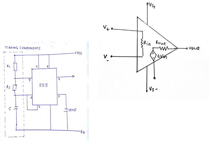
Fig. 2. Ic 555
B. Operational Amplifier
Operational Amplifier commonly known as OpAmp is a linear device fundamentally used as voltage amplifier.The feedback components decide the function or operation.The circuit operates on dual power supply +Vcc and -Vee.
One input is called Non inverting(+) whereas other is called Inverting(-).The output is the difference between the two input signals applied at the terminals
III. WORKING
The operation of circuit goes through two stages:
First, amplifying of electrical signal and PWM (pulse width modulation).
In practical audio input signal is taken through microphone which converts it into electrical signal. For simulation purpose input is considered to be sinusoidal wave.We need to remove the DC component of the electrical signal thus a electrolyte capacitor is used and then fed to the TL071 opamp(low noise).
The basic modes of operation of IC 555 timer are-Monostable mode as a precision timer, Bistable mode for flip flop type switching action, and astable mode as an oscillator circuit to produce a stable output frequency adjusted by RC tank circuit.
Amplified output is fed to the control pin 5 of 555 timer IC working in astable mode. The control voltage can be varied as desired which affects the width of the output pulse.The input audio voltage is modulated with carrier generated by IC 555 which drives the loudspeaker that is conversion of complex electrical analog signal to soundwave.
IV. NGSPICE CODE
1) R-S flip Flop: * RS flip flop
.include nand.cir
.subckt rsff 1 2 3 6 7 xnand1 1 3 4 nand xnand2 2 3 5 nand xnand3 4 7 6 nand xnand4 5 6 7 nand
.ends
2) Nand Gate: *NAND Gate
.model mosn NMOS
.model mosp PMOS
.subckt nand 2 3 4
Vdd 1 0 dc 5V
M1 4 2 1 1 mosp
M2 4 3 1 1 mosp
M3 4 2 6 6 mosn
.ends
Fig. 4. Audio Amplifier
3) Comparator: *comparator
.subckt comp 6 1 4 R1 1 0 10k
.model bjt npn Q1 2 1 5 bjt R2 5 3 10k
R3 2 7 910E
Q2 7 6 5 bjt
R4 6 0 10k
.model bjt1 pnp Q3 4 7 2 bjt1 R4 4 0 4K7 Vcc 2 0 dc 12V Vee 3 0 -12V
.ends
4) Amplifier: *opamp subckt
.subckt opamp 1 2 6 101 102 Rin 1 2 10Meg
E1 3 0 1 2 100k
R1 3 4 1k
C1 4 0 15u
E2 5 0 4 0 1k
R2 5 6 10
.ends
5) IC Timer: *555 timer*
.include lastattempt.cir
.include inver.cir
.include rsff.cir
.model bjt1 npn
.model bjt2 pnp
.subckt timer 12 15 13 4 6 5 8
Vcc 1 0 dc 12v
V1 14 0 dc -12v
R1 1 2 10k
R2 2 3 10k
R3 3 4 10k
Q1 4 7 0 bjt1
Q2 7 6 5 bjt2
xinver 7 8 inver
xcomp1 12 15 9 comp
xcomp2 13 3 10 comp
xrsff 9 10 4 7 11 rsff
.ends
A. Audio Amplifier
*audio amplifier*
.include timer.cir
.include lastopamp.cir
Vin 1 0 sin(0 5 1k 0 0)
C1 1 2 1u
R1 3 2 47k
R3 2 0 47k
xopamp 2 5 4 3 0 opamp
R4 4 5 22k
C2 5 6 10u
R5 6 0 1k
C3 4 7 1u
R8 7 8 1k
C4 9 0 10u
d1 9 10
R2 3 9 10k
Rl 12 0 3k
C5 11 12 10u
Vcc 3 0 dc 12v
xtimer 9 8 9 10 3 3 11 timer
.control
tran 0.05m 25m
run
set xbrushwidth=3;
plot V(1)
plot V(12)
.endc
.end
V. SIMULATION OUTPUTS
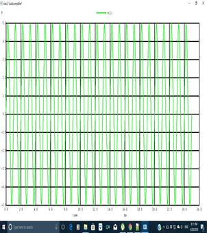
Fig. 5. Input
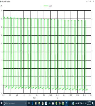
VI. OBSERVATIONS
The input signal is a sine wave of Vpp 10V i.e from -5V to +5V Whereas the output is a square wave with varying width of amplitude +16V.
VII. CONCLUSION
Microphone is a transducer to convert audio signal to electrical signal
The amplified signal is input to IC 555 working in astable mode.Pulse width Modulation starts when at pin 5 a low frequency signal is applied
Speaker responds to d.c value of modulated output.Hence audio signal is modified.
A. Applications
Developing low power music system that can be used in limited areas like in a vehicle or classrooms.
Generation of carrier frequency for modulation of low audio signals.
B. Future Scope
Circuit expansion for high power loud speakers.
Sound operated switch.
C. Limitations
The timer cannot produce a 50 percent duty cycle signal.
A complex demodulation circuit will be required.
This circuit is theoretical and may require changes in hardware implementation.