Home > Analog CMOS Design > MOSFET Parasitics > Interconnect Capacitance
Interconnect Capacitance :
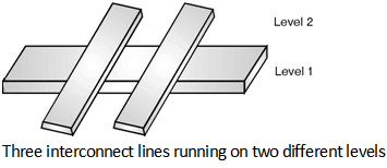
In VLSI integrated it is difficult to estimate the circuits interconnect capacitance of the circuits. As shown in Figure below the interconnect is a three dimensional which includes, shape, thickness and vertical distances.
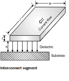
Consider the section of a single interconnect which is shown in below Figure.
Here, the wire has length l in the current direction, width of w and thickness of t. Using the basic geometry of Figure below the capacitance can be modelled as a parallel plate capacitor.
Under these circumstances the total capacitance of the wire can be given as,
CPP = w×l
Where, ÃŽdi represents the permittivity of the dielectric placed between interconnect and substrate.
For integrated circuits the dielectric used is generally SiO2. In order to reduce the effect of this parasitic capacitance the width of the wire can be reduced. The parallel plate capacitor model is simple and inaccurate when the width of the wire is too small. Under these conditions the capacitance between the side walls of the wire and the substrate is considered. This type of capacitance is called as the fringing capacitance.
Figure below shows the effect of fringing electric field upon the parasitic wire capacitance.
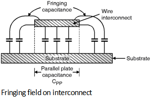
The effect of fringing capacitance can be modelled as,
Cfringe =
Thus the total parasitic capacitance of the interconnect is the sum of two components i.e. CPP and Cfringe.
The parallel plate capacitor can be calculated by using the orthogonal field between the wire of width w and the ground plane, the resulting equation of parasitic capacitance of wire is,
Cwire = CPP + Cfringe
= +