Home > mini projects > DIGITAL TO ANALOG CONVERTER USING 8 BIT WEIGHTED RESISTORS
Digital to Analog Converter using 8 bit Weighted Resistors
Abstract -Giving 8 bit data as input to the summing amplifier and expecting output voltage to be analog . The circuit is found to be working satisfactorily .
I. INTRODUCTION
A digital to analog converter is a device which converts digital data to analog signal. Here the input is given in terms of 8 bit digital data to DAC and output is to be an analog voltage. Signals can be easily stored and transmitted in digital format but in order to be recognized by human or non-digital systems it should be converted to analog.
II. DESIGN AND WORKING
The WEIGHTED RESISTORS DAC circuit shown in fig.-1.If we give any analog signal in digital form of bits then number of bits is equal to the number of input weighted resistors used.As we are giving 8 bit data we will be having 8 weighted resistors in the circuit. All the 8 resistors are connected to the inverting terminal of opamp IC741 .
A switch is provided in between the input data and weighted resistors.Voltage reference is given to the 8 weighted resistors.A feedback resistor is connected between the inverting terminal and output terminal of the opamp.Vcc and ground are connected to pins of IC741 in accordamce to the datasheet.According to the value of feedback resistor used the value of weighted resistors is determined.
III. MATH
In general for an inverting opamp the output voltage is given as
V0 = Vref (-Rf/R1)
As we are using 8 bit data each bit is multiplied with corresponding voltage and finally summation of all these voltages gives the final analog output.
V0 = Vref*D0(-Rf/R0)+Vref*D1(-Rf/R1)+Vref*D2(-Rf/R2)+ Vref*D3(-Rf/R3)+Vref*D4(-Rf/R4)+Vref*D5(-Rf/R5)+ Vref*D6(-Rf/R6)+ Vref*D7(-Rf/R7).
By substituting the values of Rf and Ri where i = 0 to 7 we get the output voltage as
V0 = [(D0/2)+(D1/4)+(D2/8)+(D3/16)+(D4/32)+(D5/64)+
(D6/128)+ (D7/256)]*Vref.
Where Vref is taken as -5v.
IV. CIRCUIT DIAGRAM
A. Block diagram
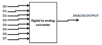
» If the switch is enabled the digital data is connected and passes through the weighted resistors and the corresponding voltage at each resistor is summed and the analog voltage is produced as output.
» As the opamp sums up the voltage levels at 8 weighted resistors it is called as summing amplifier.
» In case if the switch is disabled the resistor is grounded.
» If n bit data is given as input to digital to analog converter then 2^n voltage levels can be obtained as output.
» As we are giving 8 bit data as input we can obtain 256 different analog output voltage levels.
» The accuracy of circuit is determined by precision of weighted input resistors and the feedback resistor.
B. Circuit diagram in multisim
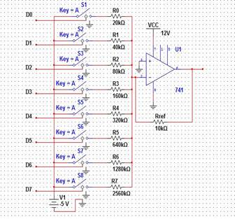
Fig 1
V.GRAPHS AND RESULTS
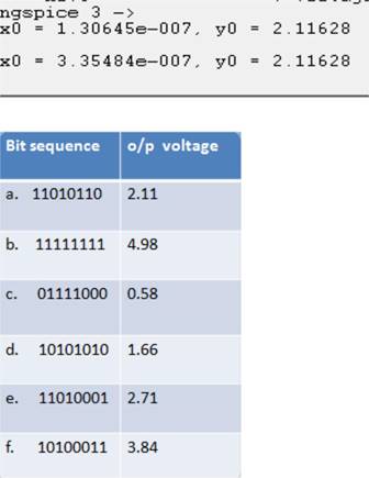
The analog output of the data 11010110 is 2.11v.

The analog output voltage is measured along the y-axis and is found to be 2.11v for the above mentioned data.
VI.CODES
*DAC*
.include dmsubcktopamp.cir
X1 2 0 3 opamp
v1 1 0 dc -5v
r1 1 2 20k
r2 1 2 40k
r3 1 2 80k
r4 1 2 160k
r5 1 2 320k
r6 1 2 640k
r7 1 2 1280k
r8 1 2 2560k
rf 2 3 10k
.tran 0 1u 100u
.control
run
plot v(3) v(1)
.endc
.end
Code for subcircuit
*op amp*
.subckt opamp 1 2 6
E1 3 0 2 1 100k
E2 5 0 4 0 1
r1 1 2 1MEG
r2 3 4 1k
r3 5 6 100
c1 4 0 1.5u
.ends opamp