The operating principle of the ramp-type DVM is based on the measurement of the time it takes for a linear ramp voltage to rise from 0 V to the level of the input voltage, or to decrease from the level of the input voltage to zero. This time interval is measured with an electronic time-interval counter, and the count is displayed as a number of digits on electronic indicating tubes.
Conversion from a voltage to a time interval is illustrated by the waveform diagram of Figure below.
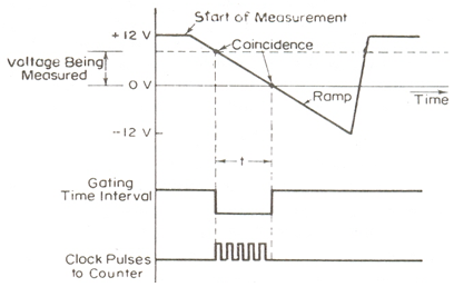
At the start of the measurement cycle, a ramp voltage is initiated; this voltage can be positive-going or negative-going. The negative-going ramp, shown in Fig. , is continuously compared with the unknown input voltage. At the instant that the ramp voltage equals the unknown voltage, a coincidence circuit, or comparator, generates a pulse which opens a gate. This gate is shown in the block diagram of below figure. The ramp voltage continues to decrease with time until it finally reaches 0 V (or ground potential) and a second comparator generates an output pulse which closes the gate.

An oscillator generates clock pulses which are allowed to pass through the gate to a number of decade counting units (DC Us) which totalize the number of pulses passed through the gate. The decimal number, displayed by the indicator tubes associated with the DCUs, is a measure of the magnitude of the input voltage.
The sample-rate multivibrator determines the rate at which the measurement cycles are initiated. The oscillation of this multi vibrator can usually be adjusted by a front-panel control, marked rate, from a few cycles per second to as high as 1,000 or more. The sample-rate circuit provides an initiating pulse for the ramp generator to start its next ramp voltage. At the same time, a reset pulse is generated which returns all the DCU s to their 0 state, removing the display momentarily from the indicator tubes.