Home > mini projects > 4 1 MULTIPLEXER
4:1 MULTIPLEXER
Abstract -In electronics, an Multiplexer is a device which transmits 2^n inputs through a single channel which is contolled by n control signals.
Multiplexer is shortened as "MUX" and it is utilized in communications systems namely,Time Division Multiplexer(TDM) based transmission systems.
I. Introduction
The multiplexer, shortened to "MUX" or "MPX", is a combinational logic circuit designed to switch one of several input lines through to a single common output line by the application of a control signal. Multiplexers operate like very fast acting multiple position rotary switches connecting or controlling multiple input lines called "channels" one at a time to the output.
The implementation of multiplexer takes three steps:
1.To get the true table of multiplexer.
2.To get the Boolean equation using the truth table by using K-Map.
3.Then, by using the above Boolean Eqaution,construct the circuit Diagram.
II. TRUTH TABLE OF 4:1 MULTIPLEXR:
The Truth table of 4:1 mux is as follows:
|
C0 |
C1 |
M |
|
0 |
0 |
X0 |
|
0 |
1 |
X1 |
|
1 |
0 |
X2 |
|
1 |
1 |
X3 |
BUILDING BOOLEAN EQUATION:
By solving the above truth table using k-map we get
the output equation as:
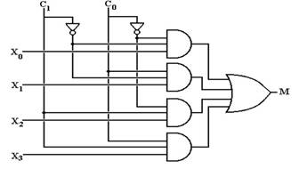
M=c0'c1'x1+c0'c1x1+c0c1'x2+c0c1x3.
Using the above Boolean Equation the circuit diagram is drawn as:
III. IMPLENTATION OF LOGIC GATES
The logic gates such as And,Not,Or and 3-input And gates implemented using mosfets.
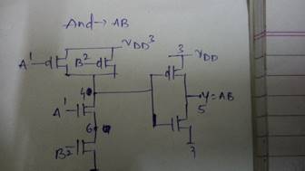
AND GATE USING MOSFETS:
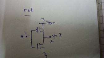
NOT GATE USING MOSFETS:
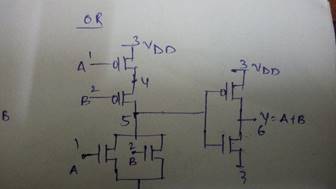
OR GATE USING MOSFETS:
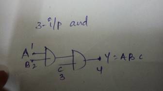
3-INPUT NAND GATE USING AND SUBCIRCUIT:
IV. MULTIPLEXER APPLICATIONS
Multiplexers are used for
•Communication Systems.
» Telephone Networks.
» Computer memory organisation
V.NETLIST
(i)NETLIST FOR AND SUBCIRCIRCUIT
.subckt and 1 2 5
.model mosfetnmos
.model mosfet1 pmos
m1 4 1 6 6 mosfet
m2 6 2 0 0 mosfet
m3 5 4 0 0 mosfet
m4 4 1 3 3 mosfet1
m5 4 2 3 3 mosfet1
m6 5 4 3 3 mosfet1
vdd 3 0 dc 5
.ends and
(ii)NETLSIT FOR OR SUB CIRCUIT
.subckt or 1 2 6
.model mosfetnmos
.model mosfet1 pmos
m1 5 1 0 0 mosfet
m2 5 2 0 0 mosfet
m3 6 5 0 0 mosfet
m4 4 1 3 3 mosfet1
m5 5 2 4 4 mosfet1
m6 6 5 3 3 mosfet1
vdd 3 0 dc 5
.ends or
(iii)NETLIST FOR NOT SUB CIRCUIT
.subckt not 1 2
.model mosfetnmos
.model mosfet1 pmos
m1 2 1 0 0 mosfet
m2 2 1 3 3 mosfet1
vdd 3 0 dc 5
.ends and
(iv)NETLIST FOR 3-INPUT AND GATE:
.subckt 3and 1 2 3 4
.include andmos.cir
x1 1 2 5 and
x2 3 5 4 and
.ends 3and
(v)NETLIST FOR MUX CIRCUIT:
4:1 mux
.include notmos.cir
.include andmos.cir
.include ormos.cir
.include 3and.cir
x1 1 3 not
x2 2 4 not
x3 3 4 5 9 3and
x4 3 2 6 10 3and
x5 1 4 7 11 3and
x6 1 2 8 12 3and
x7 9 10 13 or
x8 11 12 14 or
x9 13 14 15 or
v1 1 0 dc 5
v2 2 0 dc 5
v3 5 0 pulse(0 5 0 0 0 5u 10u)
v4 6 0 pulse(0 5 0 0 0 10u 20u)
v5 7 0 pulse(0 5 0 0 0 20u 50u)
v6 8 0 pulse(0 5 0 0 0 50u 100u)
.tran 0.25u .5m
.control
run
display
plot v(1)
plot v(2)
plot v(5)
plot v(6)
plot v(7)
plot v(8)
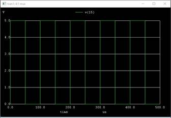
plot v(15)
.endc
.end
V. INput waveforms
As we are giving 11 as control signals we need to check whether the input signal x3 is at the output or not.
Input signal x3 is:
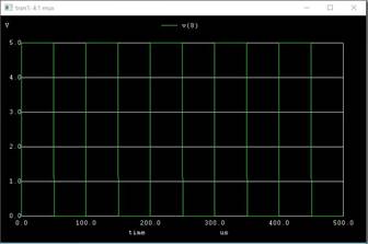
VI. output waveform