Saturating type Precision HWR
In positive half cycle, output of op-amp is positive so diode D is forward biased.
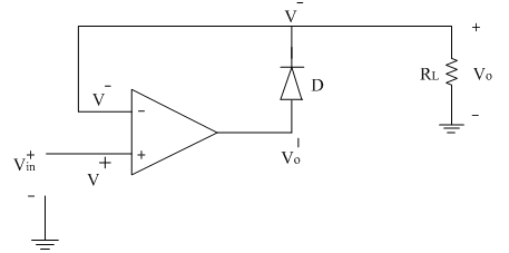
From the above circuit diagram
V^+=Vin
V^-=Vo
The output of op-amp is given by
Vo^’=A [V^+ – V^- ]
Vo^’=A [Vin – Vo ]
Now from KVL
Vo^’=VD+Vo
Comparing the above two equations of Vo^’
A[Vin-Vo ]=VD+Vo
AVin-AVo=VD+Vo
AVin=VD+Vo+AVo
AVin=VD+Vo (A+1)
AVin=VD+Vo A (since.. (A+1) ≈ A)
A[Vin-Vo ]=VD
Vin-Vo=VD/A≈0 (Since ..A is very large)
∴Vin=Vo
In negative half cycle, output of op-amp is negative so diode 'D' is reverse biased. Thus op-amp is in open loop configuration & goes into saturation. In negative half cycle, input voltage magnitude is negative.
∴Vo^’=-Vsat
And output voltage across load is zero
∴Vo=0 V
Thus in negative half cycle op-amp goes into negative saturation. This type of rectifier is called Saturating type of precision half wave rectifier.
Limitation:
The op-amp takes long time to come out of saturation and to go back in linear range. Time of one cycle depends on the frequency of input signal. If input frequency is very high, the time duration of the negative half cycle is very small. So it is not possible for op-amp to come out of negative saturation. Thus this type of circuit is suitable for low frequency input signals.
To overcome this problem, non-saturating type of precision half wave rectifiers are suitable for low as well as high frequency signals.
The transfer characteristic of the above rectifier is shown below.
