Multivibrators are regenerative circuits, which are mainly used in timing applications. Based on their operational characteristics, they are classified into three categories.
1. Astablemultivibrator [Free running oscillator]
2. Monostablemultivibrator[Mono/Single -shot]
3. Bistablemultivibrator
In multivibrators, op-amp have two states only i.e. ±Vsat
AstableMultivibrator:
Both the states at the output of an op-amp are temporary states. None of them is a permanent state. If output is HIGH, after some time it changes to LOW without any triggering pulse. Thus output is a square wave which is continuously toggling between HIGH and LOW states and hence the name astable.
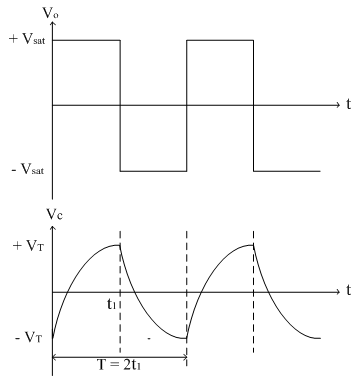
The following figure shows astable multivibrator using op-amp.

The output voltage is either +Vsat (HIGH) or –Vsat (LOW).The threshold voltage for the op-amp comparator is ±VT.
It is given as
VT=R2/(R1+R2 ) Vout
VT=β.Vout
Where β=R2/(R1+R2 ) is the feedback factor.
When output is +Vsat, the threshold is positive i.e.
+VT=R2/(R1+R2 ) (+V_sat )
When output is -Vsat, the threshold is negative i.e.
-VT=R2/(R1+R2 ) (-Vsat )
Thus +VT and –VT are the two triggering points are available
The voltage across capacitor C is input to the op-amp and the second input is the triggering point ±VT. So the voltage across capacitor, Vc is compared with the threshold VT(i.e. triggering point).
Let at t = 0, output just changes to +Vsat so capacitor starts charging through resistance R towards +Vsat with an initial voltage of -VT. The voltage across capacitor and output waveform is shown in figure below.
The voltage across capacitor C is given as
Vc=Vfinal+[Vinitial-Vfinal ] e^((-t)⁄RC)
Where final value =+Vsat
Initial value =-VT
∴Vc=Vsat-[VT+Vsat ] e^((-t)⁄RC)
When voltage across capacitor is more positive(i.e. crossing the threshold +VT) with respect to +VT, output state changes to -Vsat
When capacitor voltage is more negative with respect to negative threshold -VT output state changes to +Vsat.
The time constant ‘RC’ is same while charging and discharging towards +Vsat and –Vsat respectively. So output square wave is symmetrical with 50% duty cycle.
Since the charging and discharging time is same, the total time of one cycle is
T=2t1
From the waveforms shown above,
At time t = t1, the voltage across capacitor C is
∴VT=Vsat-[VT+Vsat ] e^((-t1)⁄RC)
[VT+Vsat ] e^((-t1)⁄RC)=Vsat-VT
e^((-t1)⁄RC)=(Vsat-VT)/(VT+Vsat )
But the threshold point VT is
VT=R2/(R1+R2 ) Vsat
∴e^((-t1)⁄RC)=(Vsat-R2/(R1+R2 ) Vsat)/(Vsat+R2/(R1+R2 ) Vsat )
∴e^((-t1)⁄RC)=(Vsat [1-R2/(R1+R2 )])/(Vsat [1+R2/(R1+R2 )] )
∴e^((-t1)⁄RC)=[(R1+R2-R2)/(R1+R2 )]/[(R1+R2+R2)/(R1+R2 )]
∴e^((-t1)⁄RC)=R1/(R1+2R2 )
-t1/RC=ln[R1/(R1+2R2 )]
∴t1=-RC ln[R1/(R1+2R2 )]
Absorbing the negative sign
t1=RC ln[(R1+2R2)/R1 ]
t1=RC ln[1+2R2/R1 ]
But the total time T is T=2t1
∴T=2RC ln[1+2R2/R1 ]
The output frequency ‘f’ is given as
f=1/T
∴f=1/(2RC ln[1+2R2/R1 ] )
Input to the op-amp is either +VT or –VT. So differential input voltage to the op-amp must be 2VT. While designing the circuit, this must be considered.
As VT=R2/(R1+R2 ) Vsat select R1 and R2 properly.
If we select R2 =0.86R1, the time of output cycle is T=2RC. Thus with above condition, we can change output frequency by changing only R and C
To change the output duty cycle, the threshold points are adjusted to different values. This is done by adding an additional battery of voltage ‘V’ in feedback path as shown in figure below. By this we can change TON and TOFF times and hence duty cycle.
If we connect a variable supply ‘V’, the triggering points can be varied and hence the duty cycle also. In such case the above circuit is termed as Voltage controlled Oscillator (VCO)