The following figure shows op-amp as the inverting amplifier.
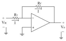
The non-inverting terminal is at ground potential. Due to virtual ground concept, the inverting terminal is also appears to be at ground potential.
The current 'I' can be calculated as,

Since input current to the op-amp is zero, same current 'I' flows in the feedback path also. The current 'I' is,
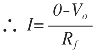
Comparing the above two equations of 'I'
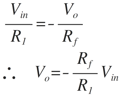
The factor Rf/R1 is the gain of the amplifier and the negative sign indicates that the polarity of output is reversed to that of input signal.
Thus the output is inverted with respect to input, which is shown with the help of negative sign. So there is a phase shift of 180̊ between input and output signal as shown in waveforms below.

Important points:
The phase shift between input and output is 180̊.
The voltage gain is dependent on the two resistances R1 and Rf. By changing the values of the two resistances required gain can be adjusted.
If Rf> R1, gain is more than 1
If Rf< R1, gain is less than 1
If Rf = R1, gain is equal to 1 i.e. unity
Thus the output voltage can be greater than, less than or equal to input voltage in magnitude.
The gain is a factor which is multiplied to input signal to get the output signal. Thus we can say that the scale of the input signal can be changed by changing the scale of the amplifier i.e. the gain. Hence the circuit is also called as scale changer. If the gain is 1 it is called as phase inverter.