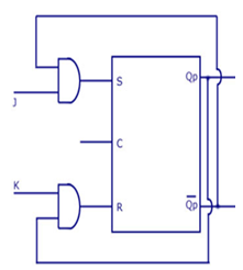
As told earlier, J and K will be given as external inputs to S and R. As shown in the logic diagram below, S and R will be the outputs of the combinational circuit.
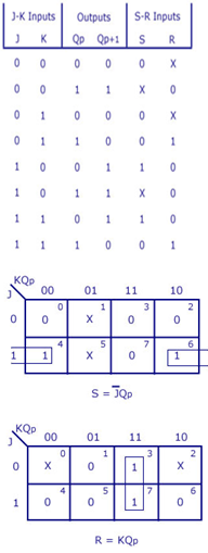
The truth tables for the flip flop conversion are given below. The present state is represented by Qp and Qp+1 is the next state to be obtained when the J and K inputs are applied.
For two inputs J and K, there will be eight possible combinations. For each combination of J, K and Qp, the corresponding Qp+1 states are found. Qp+1 simply suggests the future values to be obtained by the JK flip flop after the value of Qp. The table is then completed by writing the values of S and R required to get each Qp+1 from the corresponding Qp. That is, the values of S and R that are required to change the state of the flip flop from Qp to Qp+1 are written.