![]()
The voltage regulator is a circuit which keeps the output voltage constant under all the operating conditions. Generally output voltage changes if there is a change in input voltage, load current or temperature. Input to the voltage regulator is the unregulated pulsating dc voltage obtained from filter and rectifier. Its output is constant dc voltage which is almost ripple free. Figure bellow shows the block diagram of voltage regulator,
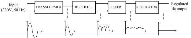
The ac voltage (230V, 50Hz) is applied to the primary of a step-down transformer. The transformer steps down the ac voltage, to the level desired for the desired dc output, with the help of a suitable turns ratio this can be achieved.
The ac voltage coming out from the transformer is applied to the rectifier circuit. This rectifier circuit converts ac voltage into pulsating dc voltage. A pulsating dc voltage means a unidirectional voltage containing large varying components called ripples in it. The filter circuit is used after the rectifier circuit which reduces the ripple content in the pulsating dc and tries to make it smoother. Still the filter output contains some ripples. This voltage is called unregulated dc voltage. After filter a regulator block is used. It removes all the ripples from filter and makes it output voltage smooth. It also keeps the output voltage constant irrespective of changes in input dc voltage. It keeps the output voltage constant under variable load conditions as well. Thus a voltage regulator is the one which is designed to keep the output voltage of a power supply nearly constant, under the varying input voltage conditions and varying load conditions.
Factors affecting the load voltage:
The various factors which affect the load voltage in a power supply are mentioned below.
1.Load current (IL):
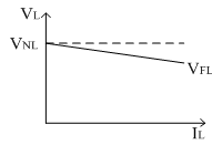
Ideally the output voltage should remain constant inspite of changes in the load current; but practically the power supply without regulator the load voltage decreases as load current, IL increases.
For practical power supply with regulator the load voltage must be constant through load changes from no load to full load condition.
2. Line voltage:
The input to the rectifier is AC (230V) i.e. line voltage. This input decides the output voltage level. If input changes output also changes. So this affects the performance of power supply. So ideally the dc output voltage must remains constant irrespective of any changes in the line voltage.
3. Temperature:
In the power supply, the rectifier unit is used which uses p-n junction diode. As the diode characteristics are temperature dependent, the overall performance of the power supply is temperature dependent.
Performance parameters of a power supply:
The performance parameters of the overall power supply is judged by specifying some parameters called as performance parameters. There are six performance parameters.
1. Line regulation:
If the input to the rectifier unit i.e. 230V changes, the output dc voltage of rectifier will also change and since the output of rectifier is applied to the regulator, the output of regulator will also vary. Thus the source cause changes in output. This is called as source regulation or line regulation. It is defined as the change in regulated dc output voltage for a given change in input (line) voltage. Ideally the source regulation should be zero and practically it should be as low as possible.
2. Load regulation:
It is defined as the change in the regulated output voltage when the load current is changed from (no load) zero to maximum value (full load) The load regulation ideally should be zero but practically it should be as small as possible. The following figure shows the load regulation characteristics.
3. Voltage stability factor (SV):
This is another factor which shows the dependency of output voltage on the input line voltage is called as voltage stability factor It is defined as the percentage change in the output voltage which occurs per volt change in input voltage with load current and temperature are assumed constant. Smaller the value of this factor, better is the performance of power supply.
4. Temperature stability factor (ST):
As in the chain of power supply we are using semiconductor devices (diodes in rectifier block) the output voltage is a temperature dependent. Thus the temperature stability of the power supply will be determined by temperature coefficients of various temperature sensitive semiconductor devices.
So it is better to choose the low temperature coefficient devices to keep output voltage constant and independent of temperature. Zener diodes are having breakdown voltages between 5V to 8V have very low temperature coefficients and hence are always preferred and used in the power supply circuits.
The value of this factor must be as small as possible and ideally it should be zero for a power supply.
5. Ripple rejection (RR):
The output of rectifier and filter consists of ripples. It is defined as a factor which shows how effectively the regulator circuit rejects the ripples and attenuates it from input to output. As ripples in the output are small compared to input, the RR is very small and in dB, it is in negative value. Practically all the performance parameters should be small for the better performance of power supply.
Types of voltage regulators:
There are basically two types of voltage regulators.
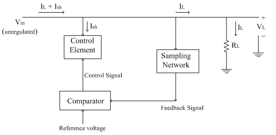
1. Shunt regulator:
The control element is the heart of the regulator circuit. If the control element is connected in shunt with the load, the regulator circuit is called as shunt voltage regulator. The unregulated input voltage Vin tries to provide the load current; but the part of the current is taken by the control element to maintain the constant voltage across the load. If there is any change in output voltage, the sampling circuit provides a feedback signal to the comparator circuit. The comparator compares the feedback signal with the reference voltage and generates the control signal which decides the amount of current required to be shunted to keep the load voltage constant. Thus control element maintains the constant output voltage by shunting the current, hence the regulator circuit is called voltage shunt regulator. Since a part of load current is captured by the control element, the control element is low current, high voltage rating component. This type of regulators are preferred for fixed voltage applications only and not for varying load conditions. The block diagram of shunt voltage regulator is shown below.
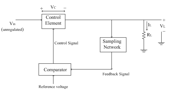
2. Series voltage regulator:
If the control element is connected in series with the load, the circuit is called series voltage regulators.
The unregulated dc voltage is the input to the circuit. The control element controls the amount of input voltage that is going to the output side.
The sampling circuit provides the necessary feedback signal. The comparator circuit compares the feedback signal with the reference voltage to generate the appropriate control signal.
Thus depending upon the value of control signal, the voltage Vcacross the control element is adjusted in order to maintain the output voltage constant. In series regulator, the entire current passes through the control element and hence control element is high current and low voltage rating components. As input and output currents are same, the efficiency depends on the output voltage. It provides good regulation than shunt regulators. It is generally used for both fixed as well as variable load conditions. The block diagram of series voltage regulator is shown below.