Home > Digital CMOS Design > CMOS Inverter > Dissipation due to Direct Path Currents
Dissipation due to Direct Path Currents
In the CMOS inverter in calculating the dynamic power dissipation we have neglected the rise and fall times of the input signal.
If we consider the finite value for rise and fall times a direct path between VDD and ground is created for a short period of time and forms another components in power dissipation called as direct current path power dissipation. The direct path current component is as shown in Figure.
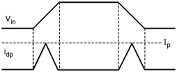
Fig-Dissipation-due-to-Direct-Path-Currents
Hence the energy consumed due to direct current path is given as,
Energy consumed in direct path = VDD * Ip tdp2 + VDD Ip tdp2
= tdp * VDD * Ip
Thus, the average power consumption due to direct path is given as,
Pdp = tdp * VDD * Ip * f
where tdp represents the transition time when both devices are conducting. Ip represents the peak current of the spike and f represents the switching frequency. The tdp in terms of rise and fall times is given by,
tdp = VDD – 2VtVDD trise / fall0.8
and Ip is the saturation current of the MOSFETS, Vt is the threshold voltage and trise/fall is the rise /fall times of the input waveform.