Depending upon the direction of the output current and voltage, the converters can be classified into five classes namely
• Class A [One-quadrant Operation]
• Class B [One-quadrant Operation]
• Class C [Two-quadrant Operation]
• Class D Chopper [Two-quadrant Operation]
• Class E Chopper [Four-quadrant Operation]
Class A [One-quadrant Operation]
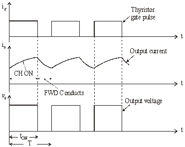
• Class A Chopper is a first quadrant chopper
• When chopper is ON, supply voltage V is connected across the load.
• When chopper is OFF, vO = 0 and the load current continues to flow in the same direction through the FWD.
• The average values of output voltage and current are always positive. Class A Chopper is a first quadrant chopper
• When chopper is ON, supply voltage V is connected across the load.
• When chopper is OFF, vO = 0 and the load current continues to flow in the same direction through the FWD.
• The average values of output voltage and current are always positive.
• Class A Chopper is a step-down chopper in which power always flows form source to load.
• It is used to control the speed of dc motor.
• The output current equations obtained in step down chopper with R-L load can be used to study the performance of Class A Chopper.
Figure below shoes Class A chopper.

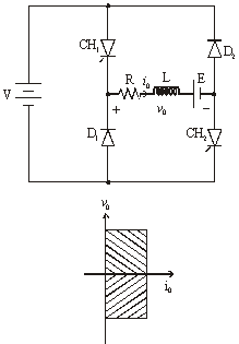
Class B [One-quadrant Operation]
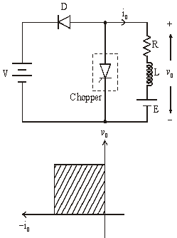
• Class B Chopper is a step-up chopper
• When chopper is ON, E drives a current through L and R in a direction opposite to that shown in figure.
• During the ON period of the chopper, the inductance L stores energy.
• When Chopper is OFF, diode D conducts, and part of the energy stored in inductor L is returned to the supply.
• Average output voltage is positive. Average output current is negative.
• Therefore Class B Chopper operates in second quadrant.
• In this chopper, power flows from load to source.
• Class B Chopper is used for regenerative braking of dc motor.
Figure below shoes Class B chopper.
Class C [Two-quadrant Operation]
• Class C Chopper can be used as a step-up or step-down chopper
• Class C Chopper is a combination of Class A and Class B Choppers.
• For first quadrant operation, CH1 is ON or D2 conducts.
• For second quadrant operation, CH2 is ON or D1 conducts.
• When CH1 is ON, the load current is positive.
• The output voltage is equal to ‘V’ & the load receives power from the source.
• When CH1 is turned OFF, energy stored in inductance L forces current to flow through the diode D2 and the output voltage is zero.
• Current continues to flow in positive direction.
• When CH2 is triggered, the voltage E forces current to flow in opposite direction through L and CH2 .
• The output voltage is zero.
• On turning OFF CH2 , the energy stored in the inductance drives current through diode D1 and the supply
• Output voltage is V, the input current becomes negative and power flows from load to source.
• Average output voltage is positive
• Average output current can take both positive and negative values.
• Choppers CH1 & CH2 should not be turned ON simultaneously as it would result in short circuiting the supply.
• Class C Chopper can be used both for dc motor control and regenerative braking of dc motor.
Figure below shoes Class C chopper.
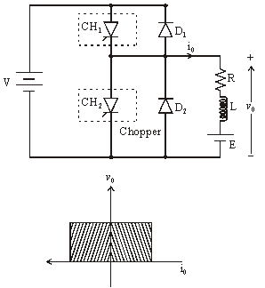

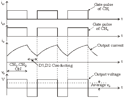
Class D Chopper [Two-quadrant Operation]
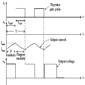
• Class D is a two quadrant chopper.
• When both CH1 and CH2 are triggered simultaneously, the output voltage vO = V and output current flows through the load.
• When CH1 and CH2 are turned OFF, the load current continues to flow in the same direction through load, D1 and D2 , due to the energy stored in the inductor L.
• Output voltage vO = – V.
• Average load voltage is positive if chopper ON time is more than the OFF time
• Average output voltage becomes negative if tON < tOFF .
• Hence the direction of load current is always positive but load voltage can be positive or negative.
Figure below shoes Class D chopper.
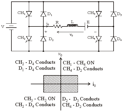
Class E Chopper [Four-quadrant Operation
• Class E is a four quadrant chopper
• When CH1 and CH4 are triggered, output current iO flows in positive direction through CH1 and CH4, and with output voltage vO = V.
• This gives the first quadrant operation.
• When both CH1 and CH4 are OFF, the energy stored in the inductor L drives iO through D2 and D3 in the same direction, but output voltage vO = -V.
• Therefore the chopper operates in the fourth quadrant.
• When CH2 and CH3 are triggered, the load current iO flows in opposite direction & output voltage vO = -V.
• Since both iO and vO are negative, the chopper operates in third quadrant.
• When both CH2 and CH3 are OFF, the load current iO continues to flow in the same direction D1 and D4 and the output voltage vO = V.
• Therefore the chopper operates in second quadrant as vO is positive but iO is negative.
Figure below shoes Class E chopper.