Home > Analog CMOS Design > CMOS Differential Amplifier > Current Mirrors
The current mirror circuits are simple current sources which gives constant current. The current mirror circuits are based on the principle that, if the gate to source voltage of two identical MOSFETs are equal then the drain current flowing through them is equal. The basic current mirror circuit is shown in Figure below.
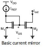
By neglecting the channel length modulation of the two transistors the drain currents can be given as :
IREF = mn Cox (VGS - V TH)2
and Iout = mn Cox (VGS - V TH)2
If we take ratio of two equations, we get,
= i.e. Iout = IREF
The key property of this circuit is that it allows precise copying of the current with no dependence of process and temperature. The ratio of I out and IREF is given by the ratio of device dimensions of two transistors.
In basic current mirror circuit we have neglected the channel length modulation. In practice for short channel devices it results in significant error in mirroring the currents.
By considering the channel length modulation effect for the basic current mirror circuit the current equations for both the transistors can be given as,
ID1 = mn Cox (VGS - V TH)2 (1 + l VDS1)
and ID2 = mn Cox (VGS - V TH)2 (1 + l VDS2)
\ = ×
Here VDS1 = VGS1 = VGS2 But, V GS2 ¹ VDS2 which results in error while copying the current from M1 to M2.
In order to suppress the effect of channel length modulation a cascode current mirror circuit is used which is as shown in Figure below.
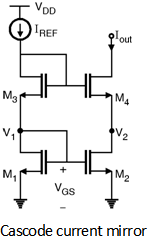
If V1 and V2 voltages are equal then Iout closely tracks the IREF i.e. Iout » IREF. In order to ensure this equality we must guarantee that
VGS4 + V2 = VGS3 + V1
Thus, if = then
VGS3 = VGS4 and V1 = V2 which gives Iout = IREF