Logic gates are the electronic circuits used to implement the digital electronic circuits. The logic gate is the heart of combinational
logic designs. Three basic logic gates, are the OR gate, the AND gate and the NOT gate. From these three logic gates other gates are derived that are NAND gate, the NOR gate, the EXCLUSIVE OR
gate and the EXCLUSIVE-NOR gate. This session mainly focus on logic gates, truth tables and Boolean expressions.
Positive/Negative Logic
The digital logic variables have two states, i.e. the logic '0' state or the
logic '1' state. These logic states are represented by two different voltage/current levels. The more positive voltage/current levels represents logic '1' and the less positive levels represents a logic '0', then the logic system is referred to as a positive logic system. On the other hand, if the more positive voltage/current levels represents a logic '0' and the less positive levels represents a logic '1', then
that logic is known as negative logic. If the two voltage levels are 0 V and +5 V, then it is positive logic system in which 0 V represents a
logic '0' and the +5 V represents a logic '1'. In the negative logic system, 0 V indicates a logic '1' and +5 V shows a logic '0'.
Truth Table
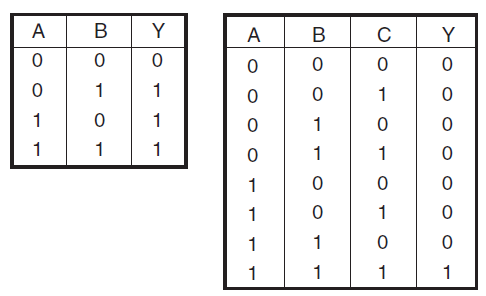
A truth table gives the combinations of input variables and the corresponding outputs of a digital circuit. The output is found from the logic expression, known as Boolean expression which relates output with the inputs.
When the number of input binary variables is only one, then only two possible inputs, i.e. '0' and '1' are available. If the inputs are two, there are four possible input combinations, i.e. 00, 01, 10, and 11. Further, for three input variables, the possible input combinations are eight, i.e. 000, 001, 010, 011, 100, 101, 110 and 111. Figure shows the truth tables of two variables and three variables.