Home > VHDL > Shift Registers > 4 bit shift register
Shift-Register
The main usage for a shift register is for converting from a serial data input stream to a parallel data output or vice versa. For a serial to parallel data conversion, the bits are shifted into the register at each clock cycle, and when all the bits (usually eight bits) are shifted in, the 8-bit register can be read to produce the eight bit parallel output. For a parallel to serial conversion, the 8-bit register is first loaded with the input data. The bits are then individually shifted out, one bit per clock cycle, on the serial output line. In general a shift register is characterized by the following control and data signals:
- Clock
- Serial input
- Asynchronous set/reset
- Synchronous set/reset
- Synchronous/asynchronous parallel load
- Clock enable
* Serial or parallel output. The shift register output mode may be:
1. Serial : only the contents of the last flip-flop is accessed by the rest
of the
circuit.
2. Parallel : the contents of one or several of flip-flops other than the
last one, is
accessed
- Shift modes: left, right, etc.
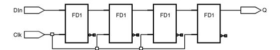 4 bit shift register :
Fig. 6.12.1 : 4 bit Shift register
library IEEE;
use IEEE.std_logic_1164.all;
entity ShiftRegister is
port ( DIn, Clk : in std_logic;
Q : out std_logic);
end ShiftRegister;
architecture Example of ShiftRegister is
begin
process (Clk, DIn)
variable DTmp : std_logic_vector(3 downto 0);
begin
if Clk'event and Clk = '1' then
DTmp := DTmp(2 downto 0) & DIn;
Q <= DTmp(3);
end if;
end process;
end Example;
1) 4-bit shift-left/shift-right register with positive-edge clock, serial
in, and
parallel out :
In this model one set the direction of shift when mode selector left_right signal is '0' then input signal shifted to left when it is '1' its direction is right.
library ieee;
use ieee.std_logic_1164.all;
entity shift_lr is
port (Clock, Sin, left_right : in std_logic;
Pout : out std_logic_vector(3 downto 0));
end shift_lr;
architecture exam of shift_lr is
signal temp: std_logic_vector(3 downto 0);
begin
process (Clock)
begin
if (Clock'event and Clock='1') then
if (left_right='0') then
temp <= temp(2 downto 0) & Sin;
else
temp <= Sin & temp(3 downto 1);
end if ;
end if ;
end process;
Pout <= temp;
end exam;
2) 4 bit, positive clock, synchronous set & clear, loadable parallel in
– parallel
out (PIPO) shift register :
library IEEE;
use IEEE.std_logic_1164.all;
entity shft_reg is
port ( CLK : in std_logic; -- Clock input CLK active high
CE : in std_logic; -- Clock enable input CE active high
CLR : in std_logic; -- Synchronous Clear input CLR active high
SET : in std_logic; -- Synchronous Set input SET active high
LOAD : in std_logic; -- Load input LOAD active high
DATA : in std_logic_vector(3 downto 0);
O : out std_logic_vector(3 downto 0));
end shft_reg;
architecture shft_reg_arch of shft_reg is
signal TEMP_O : std_logic_vector(3 downto 0);
begin
process(CLK)
begin
if rising_edge(CLK) then
if CE = '1' then
if CLR = '1' then
TEMP_O <= (others => '0');
elsif SET = '1' then
TEMP_O <= (others => '1');
elsif LOAD = '1' then
TEMP_O <= DATA;
else
TEMP_O <= '0' & TEMP_O(3 downto 1);
end if ;
end if ;
end if;
end process;
O <= TEMP_O;
end architecture;